
Build Instructions – Base Assembly – Tower Assembly – Panels and Rods – Effector Assembly – Extruder Drive
Hot End Assembly – Electronics – Bed, Top Plate and Belts – Commissioning – Printing – Troubleshooting
Goal
By the end of this section you will have fitted the front panels and connecting rods.
Front Panels
The front panels support the structure of the printer, and keep it square and stable. You will need the following parts:
| # | Component | Qty | Type | |
| 1302.1 | Front Panel | 2 | Laser cut | 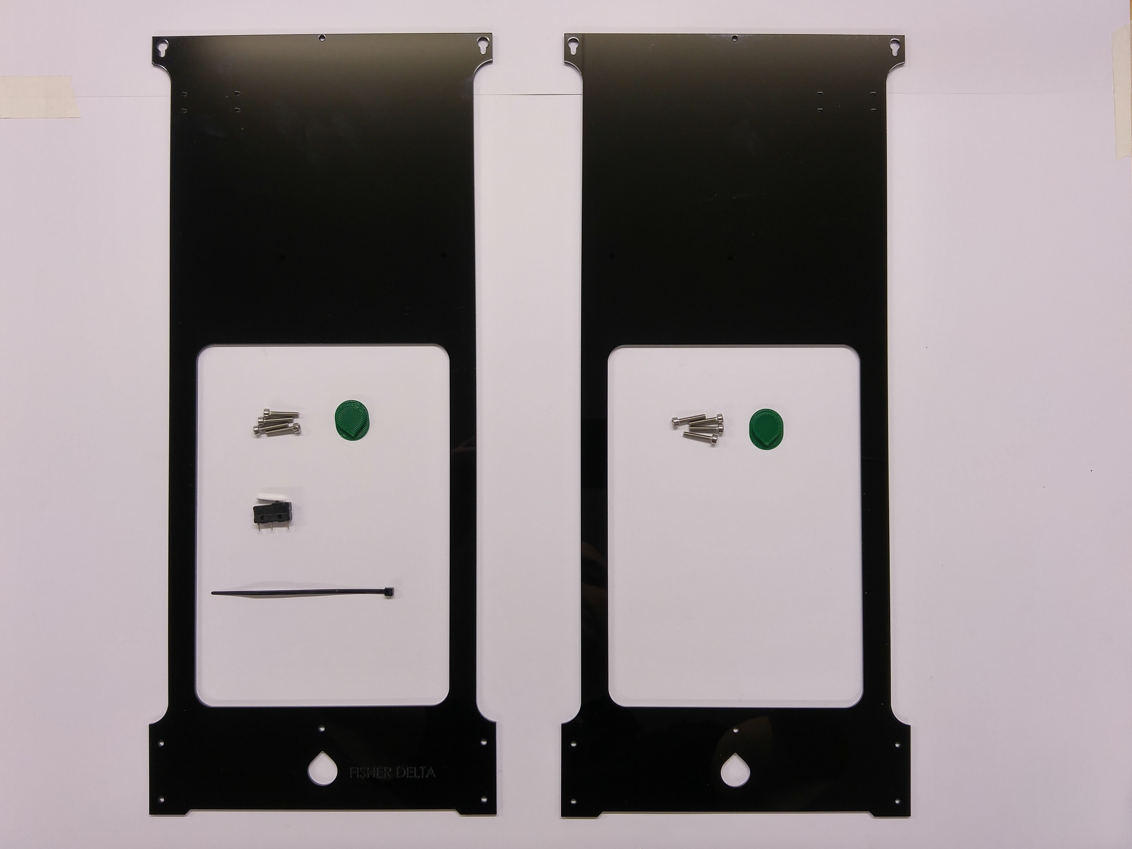 |
| 6182 | RepRap Logo | 2 | Printed | |
| 185 | Microswitch | 1 | Electronics | |
| 133 | Cable tie 2mm | 1 | Electronics |
Logo
| Peel the protective covering from the panels, then push out the acrylic parts where the printed logo will fit, if they haven’t already fallen out. | 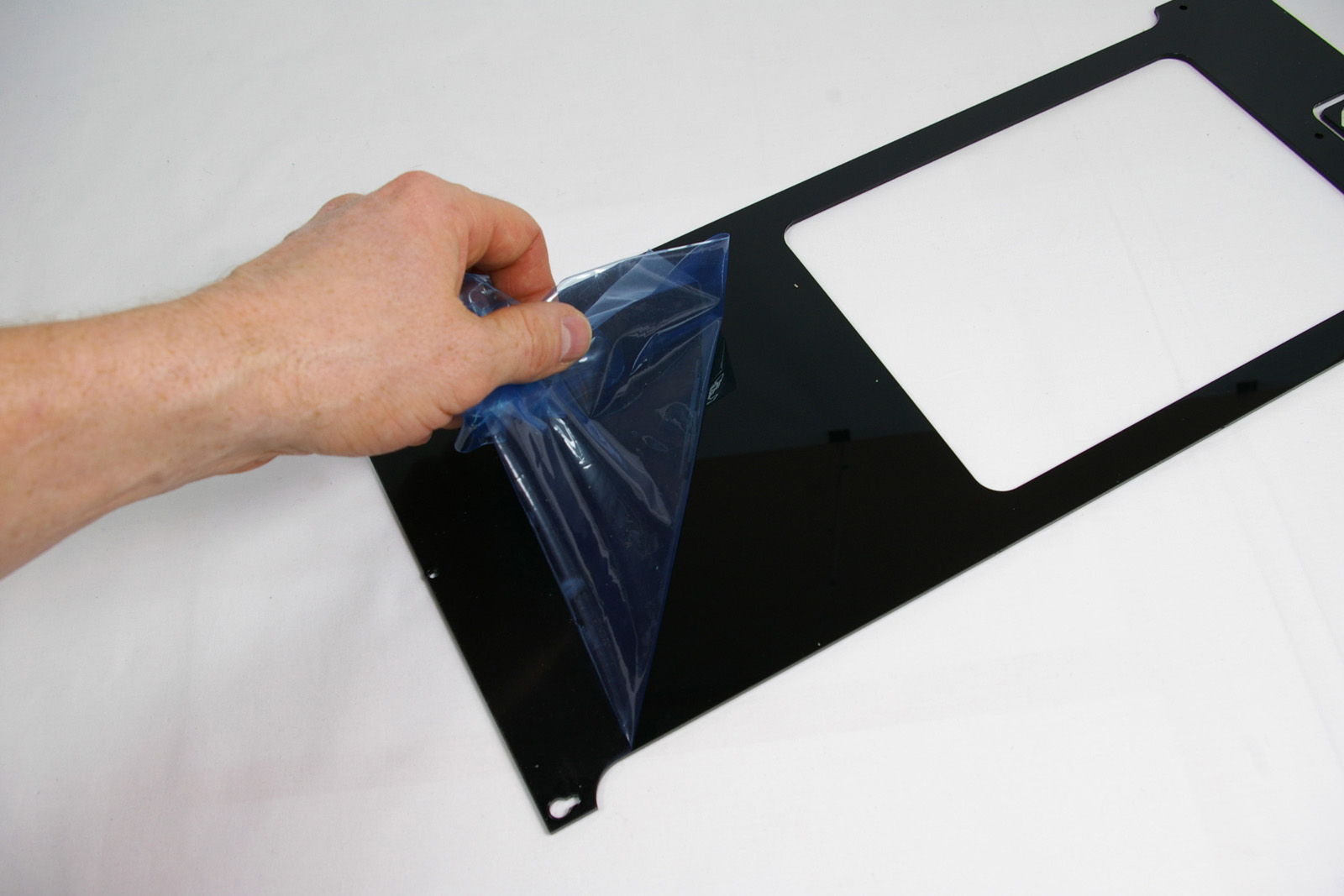 |
| Push the logo into position. This is best achieved by placing the panel face down on a flat, solid surface and gently pushing the logo into place. If it is a bit lose, secure it with small dabs of superglue on the back flange. Don’t use too much – it will discolour the black panel. | 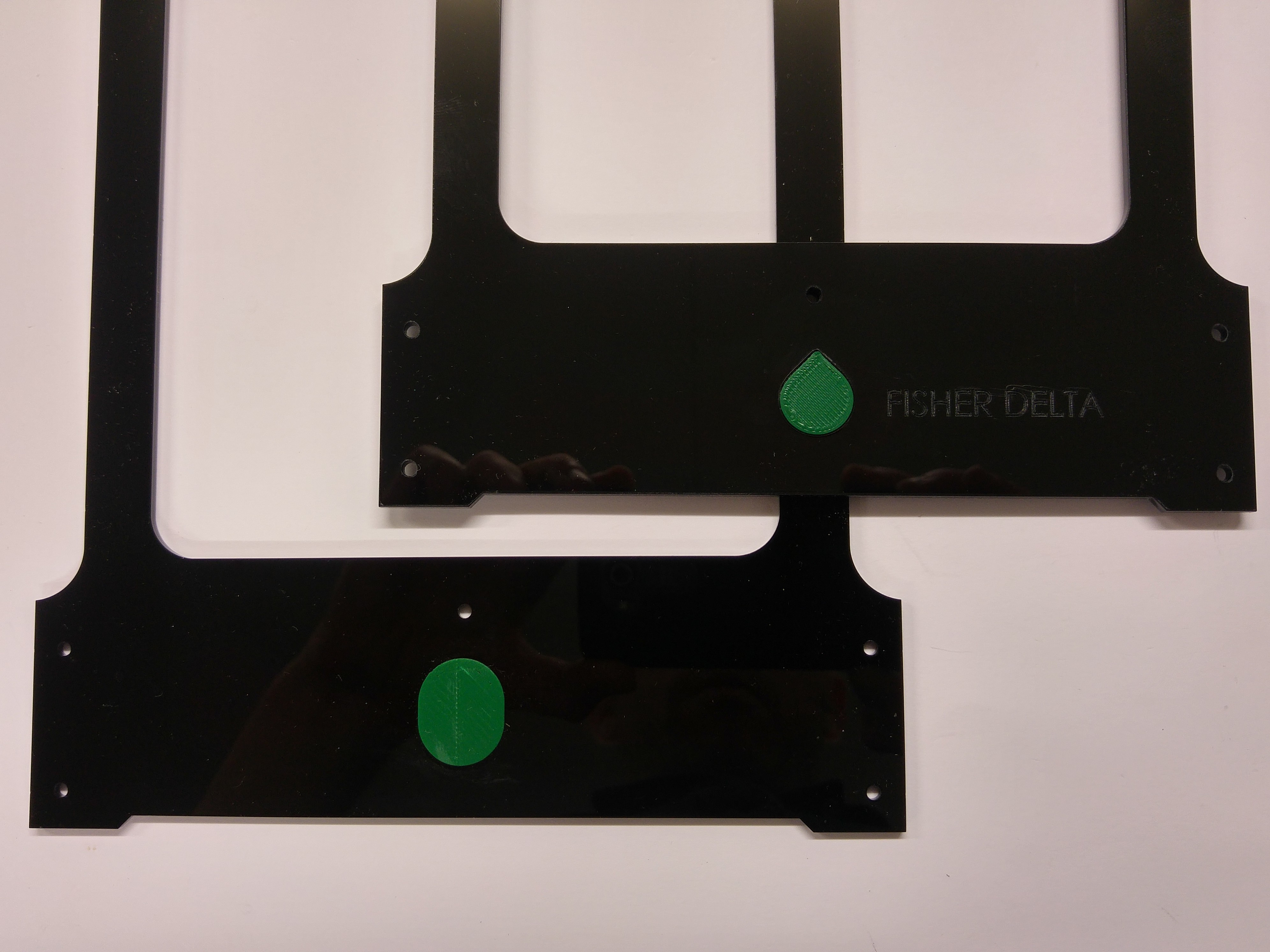 |
Endstops
The endstop is the name given to the microswitch at the end of a linear axis, or carriage. It registers when the carriage comes into contact with it, and gives the axis a known-position.
| Take one of the panels. The microswitch should fit on the top right of the back of the panel, as shown. | 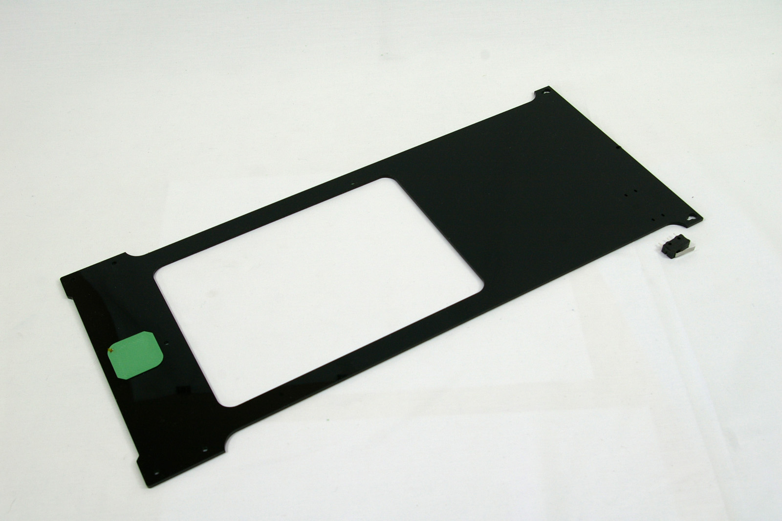 |
| The microswitch is held in place with a cable tie. Note the orientation of the microswitch, with the fulcrum of the lever downwards. Thread the cable tie from the back of the panel, through the bottom hole of the microswitch, through the panel, back in from the front of the panel, and out of the top microswitch hole. | 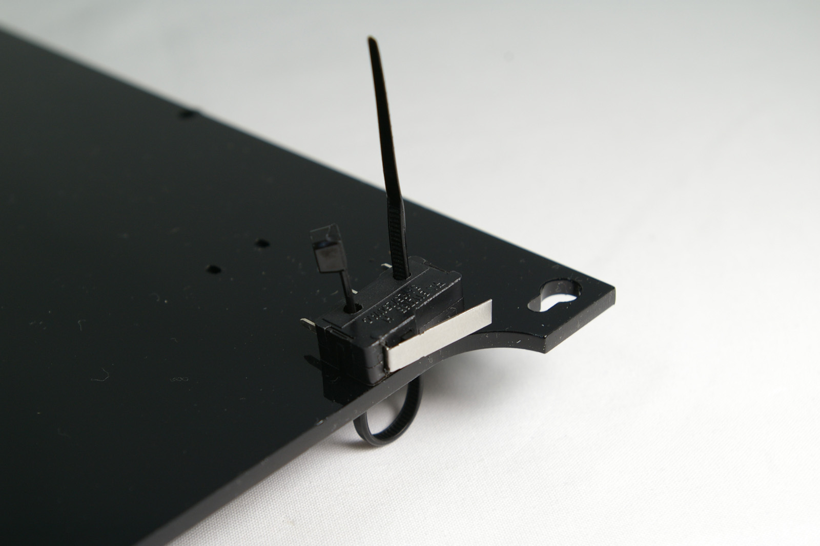 |
| Tighten the cable tie, with the head of the cable tie as close in, and towards the top of the panel. It needs to be here to keep out of the way of the carriage. | 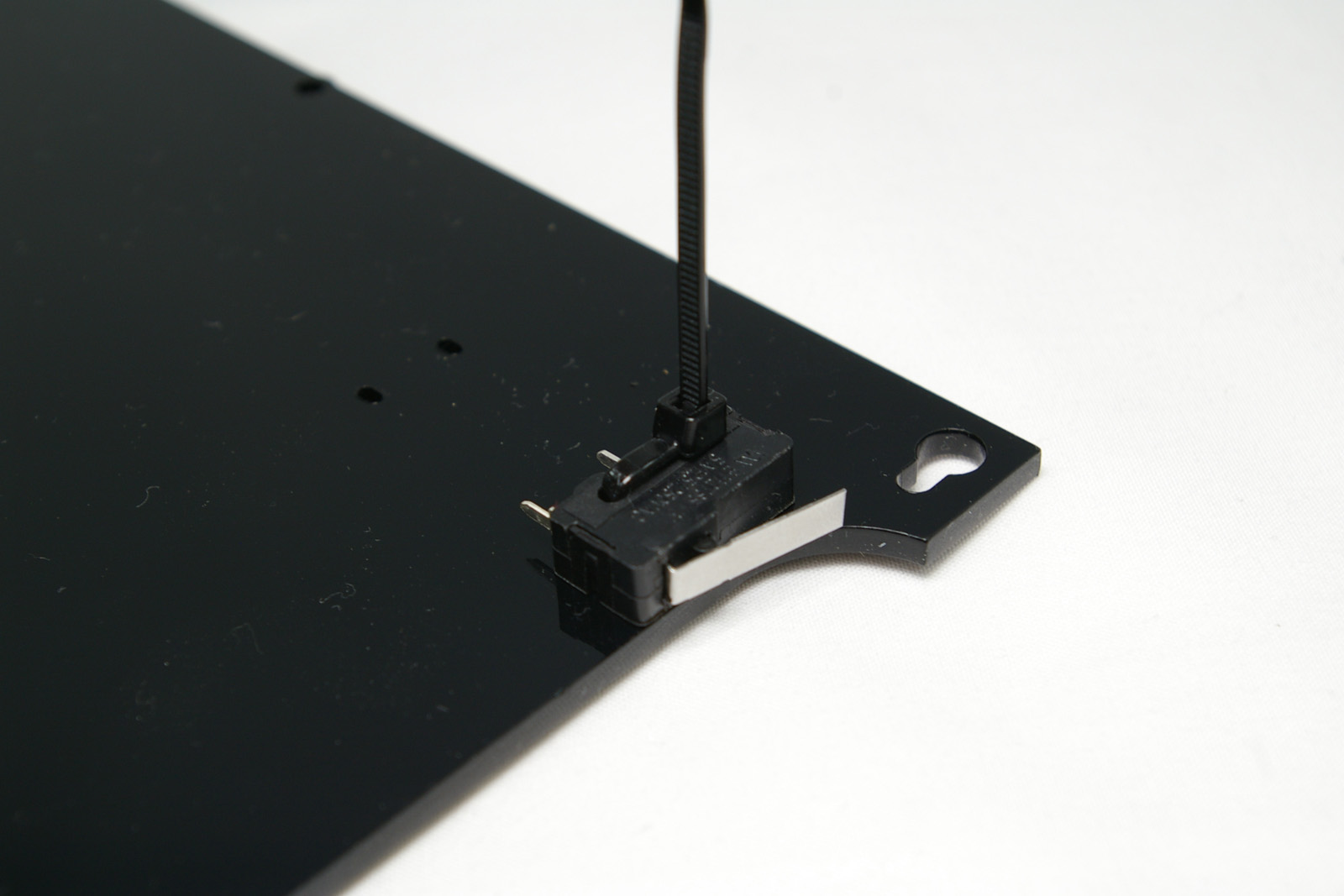 |
| Cut off the tail of the cable tie. | 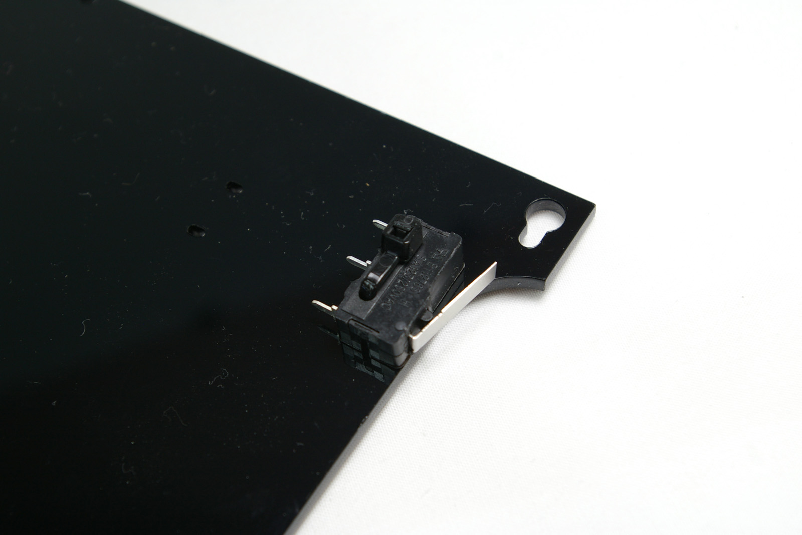 |
MasterSpool spigot and filament guide
For RepRap Fishers shipped before 1 April 2019 (1178.1) skip this step and go straight to Fitting the Panels below.
| # | Component | Qty | Type | |
| – | Panel without endstop | 1 | Assembly | 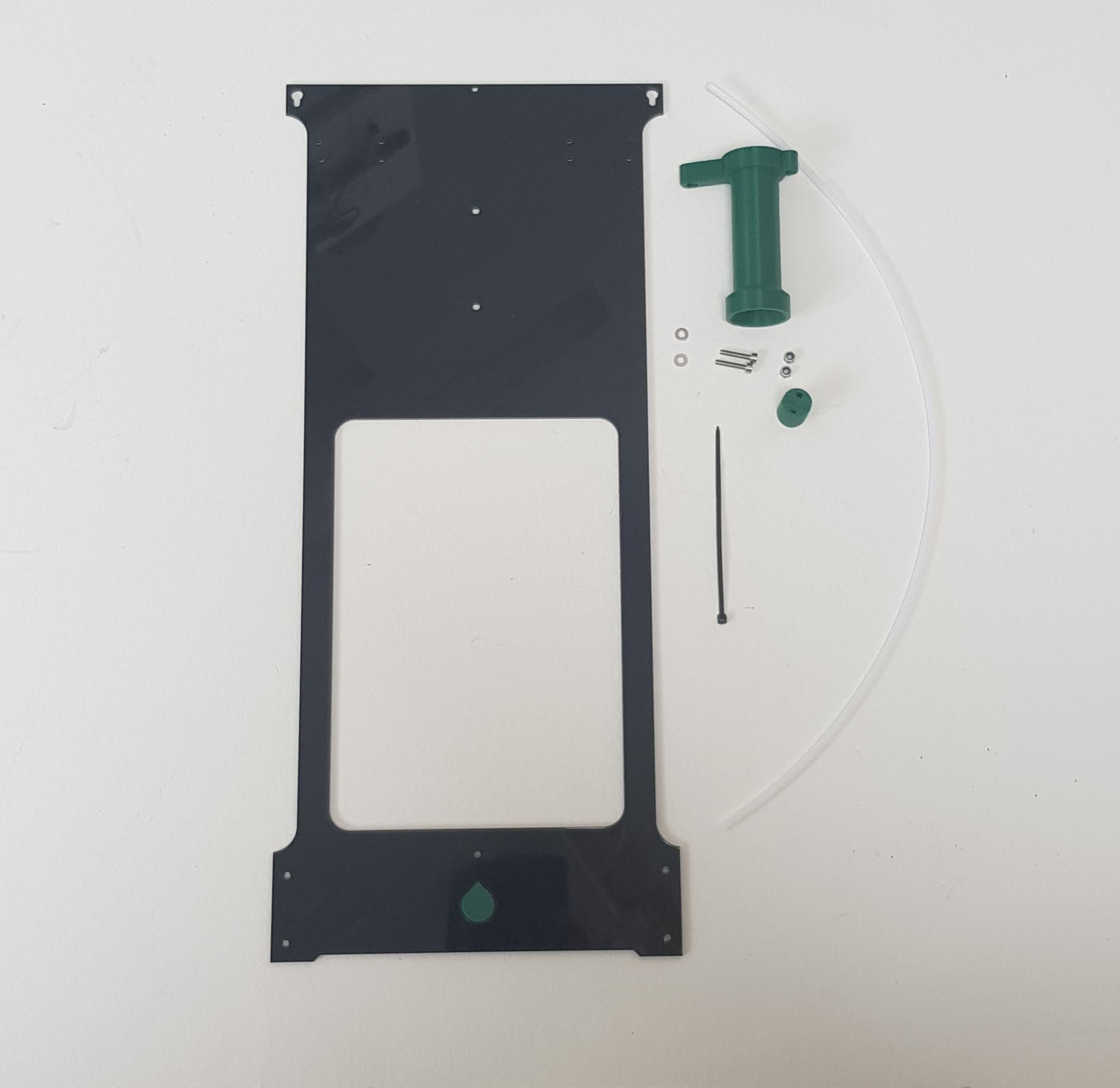 |
| 6197 | MasterSpool spigot | 1 | Printed | |
| 6199 | Filament guide spacer | 1 | Printed | |
| 242 | M3 x 16mm cap head screw | 2 | Fasteners | |
| 204 | M3 nylock nuts | 2 | Fasteners | |
| 212 | M3 washers | 2 | Fasteners | |
| 1055 | 4mm PTFE tube | 450mm | Hardware | |
| 133 | Cable ties 2mm | 1 | Electronics |
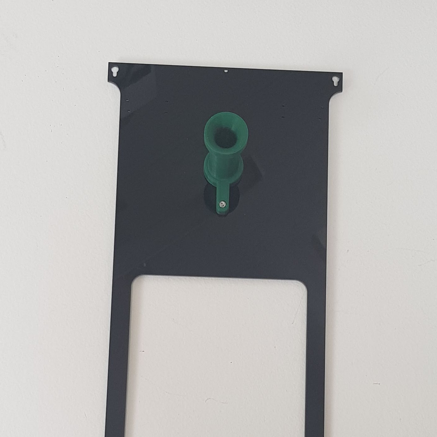
| Attach the spigot to the outside of the panel as shown using two M3 x 16 cap head screws through the spigot and panel. Fix in place using washers and nuts on the inside of the panel.
Tighten the nuts firmly, but do not over-tighten them, or you will crack the panel. |
 |
| Check the ends of the PTFE tube. If they are not neat and square, cut a short length off with a craft knife to neaten them up. | 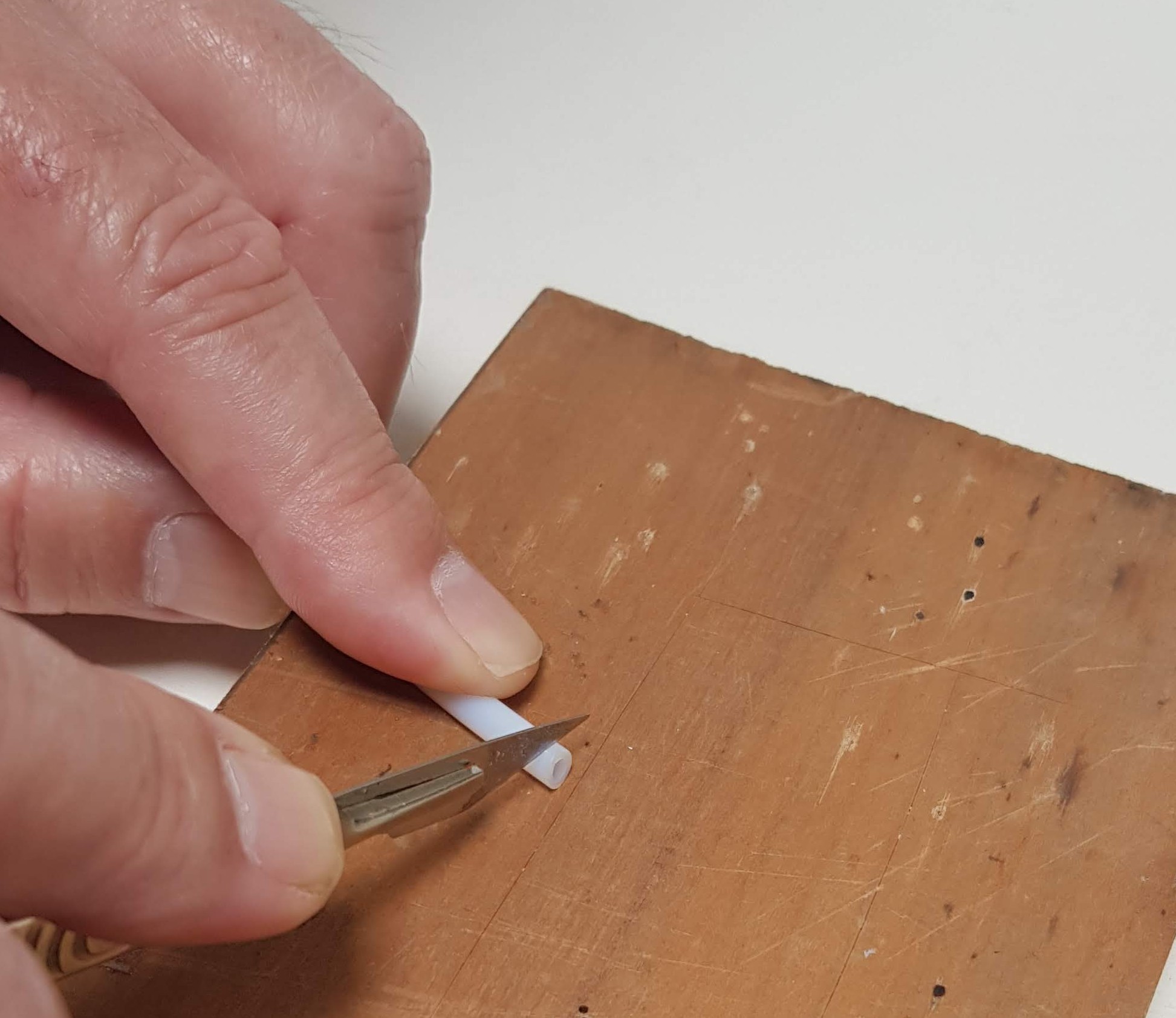 |
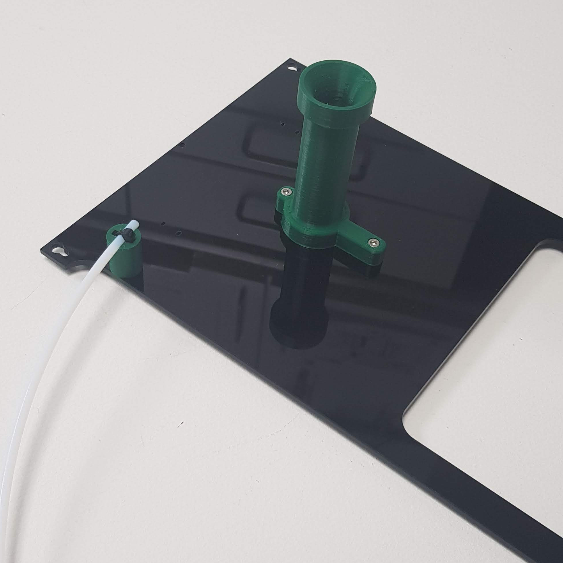
| Push a cable tie through the printed filament guide spacer from the top. The top is the end with the half-round recess. Thread the cable tie through the panel, then back through the adjacent panel hole and the other hole in the guide. Push the end of the tie loosely through its retaining gripper. Put the end of the PTFE tube through the loop you’ve created and pull the tie tight.
This should hold the PTFE firmly to the top of the spacer, and the spacer firmly to the panel. Clip off the excess end of the tie. |
 |
Fitting the Panels
| # | Component | Qty | Type | |
| – | Panel with endstop | 1 | Assembly | Awaiting photo |
| – | Panel with Spigot | 1 | Assembly | |
| 242 | M3 x 16mm cap head screw | 8 | Fasteners |
| With the Duet electronics facing you, the panel with the microswitch endstop needs to go on the left hand side, so the endstop is on the corner away from the Duet electronics on the base. See picture for correct orientation. | 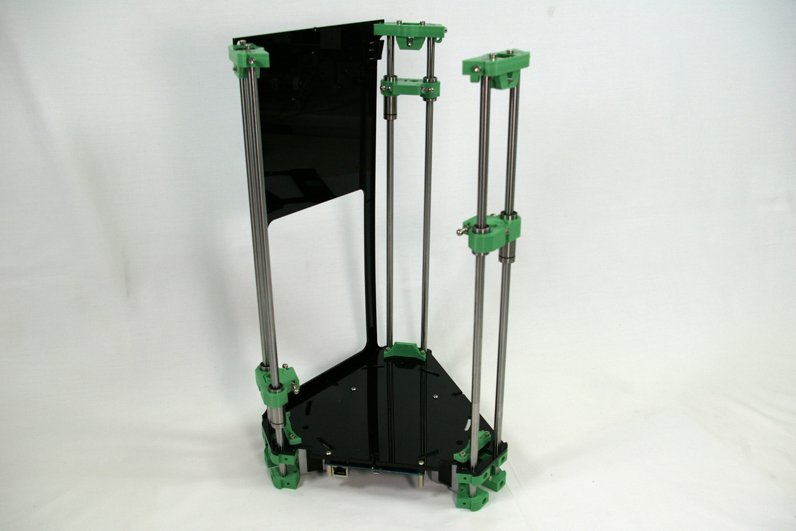 |
| Lift the base of the printer up, by resting the motors on something around 10mm thick, eg a piece of wood. The panel is longer than the rods. | 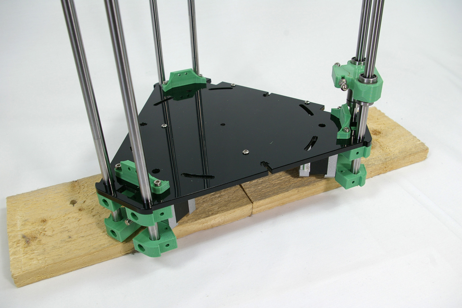 |
| Clip the panel over the cap head screws in the idler bracket at the top of the towers. You may need to slacken off the screws, so they can slide into the slot. Don’t force this; acrylic can be brittle, and may break. Ease it into position. | 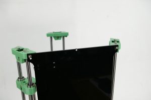 |
| Line up the four holes in the bottom of the panel with the holes in the motor mounts. Screw in four M3x16mm cap head screws to hold it in place. These self-tap into the motor mounts. | 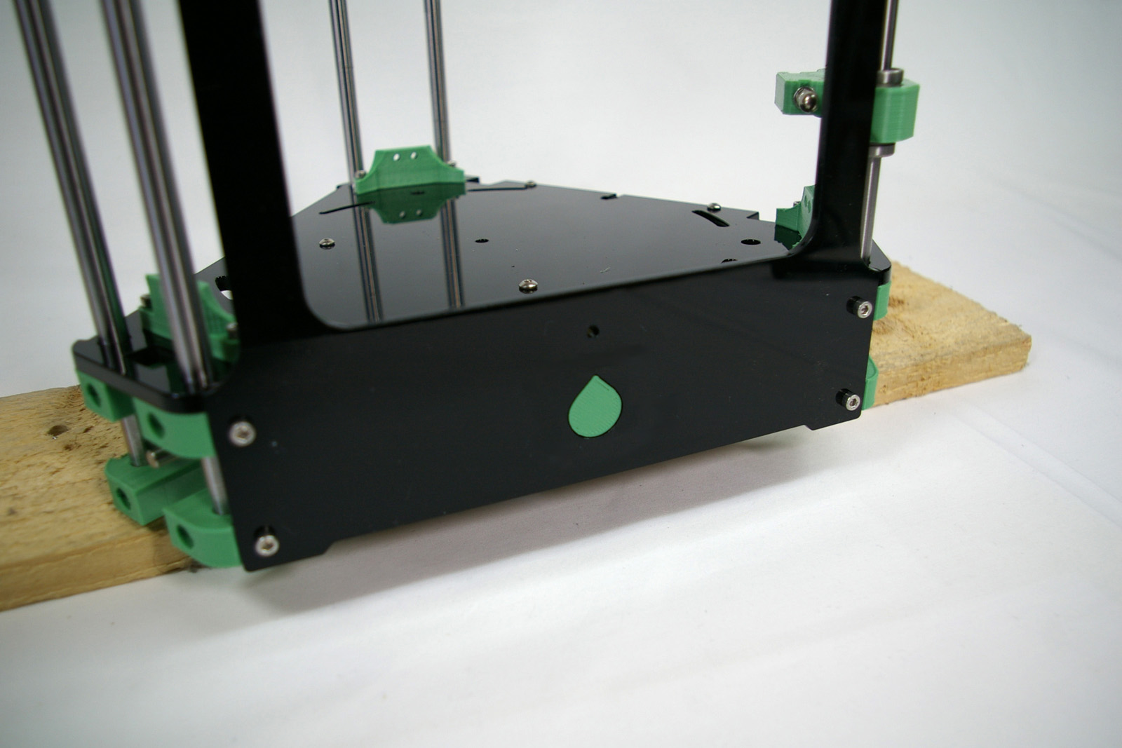 |
| At the top, the cap head screw should move into the slot. It may not be all the way down; don’t worry about this, we will adjust it later. | 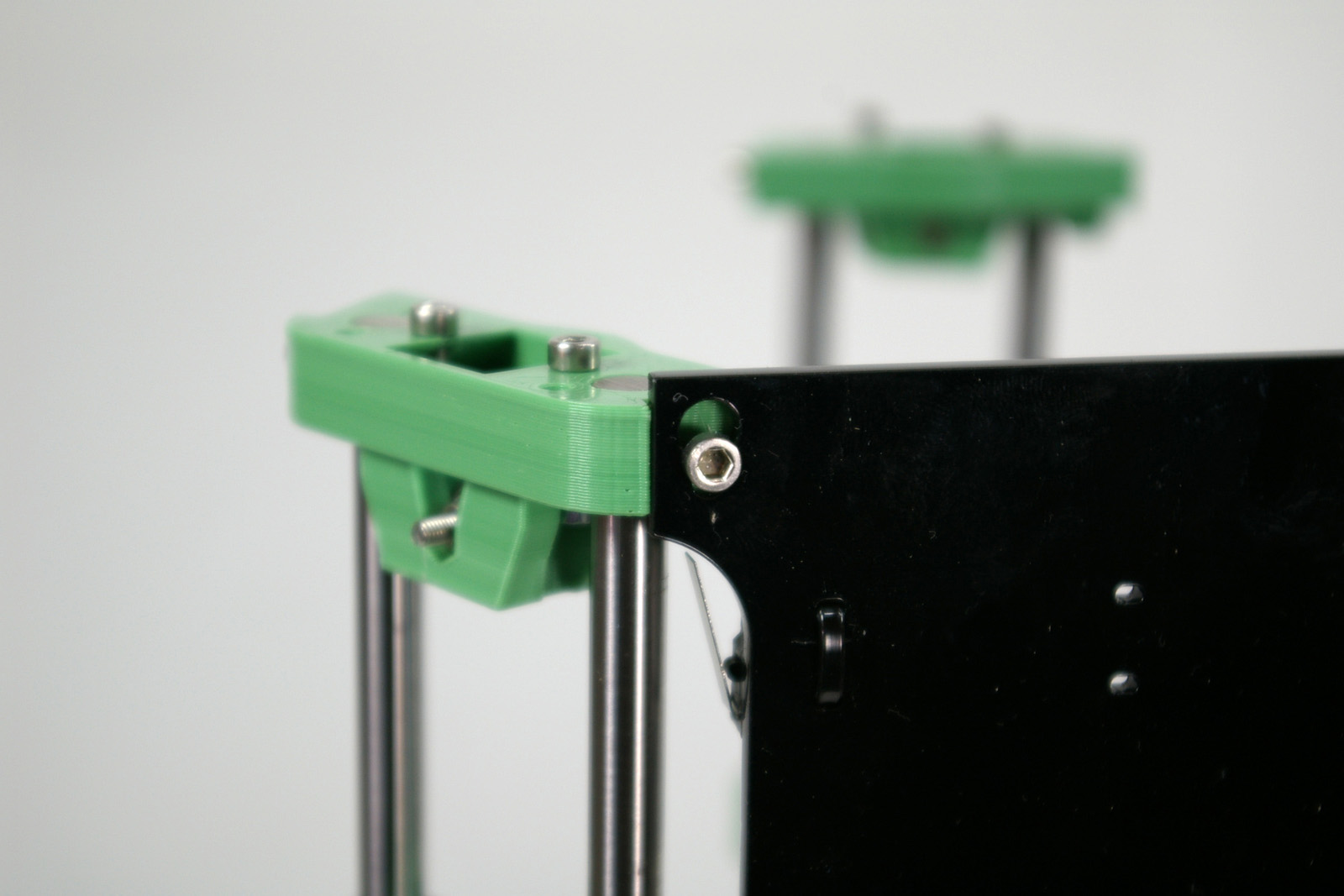 |
| Repeat the process for the second panel. This panel has the spigot and spacer.
Note that this does not cover the Duet electronics! The last panel, which covers the electronics, will be put on later. |
 |
| Again, check that the cap head screws on the idler bracket slot into the top of the panel. | 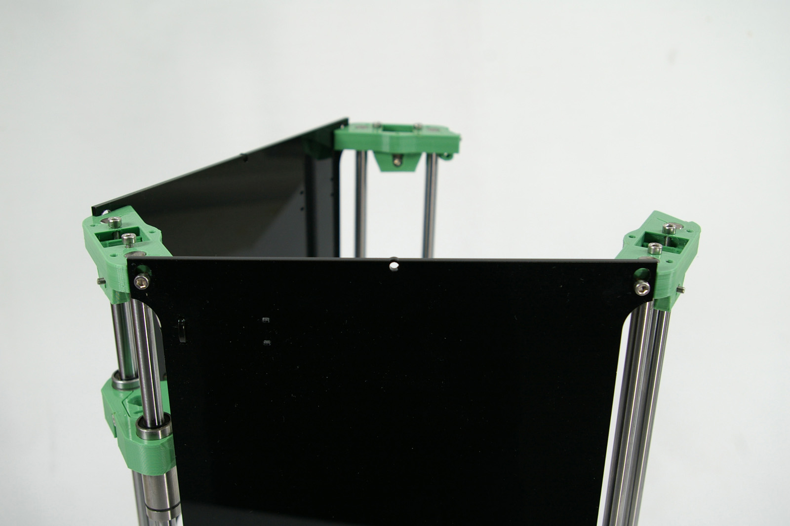 |
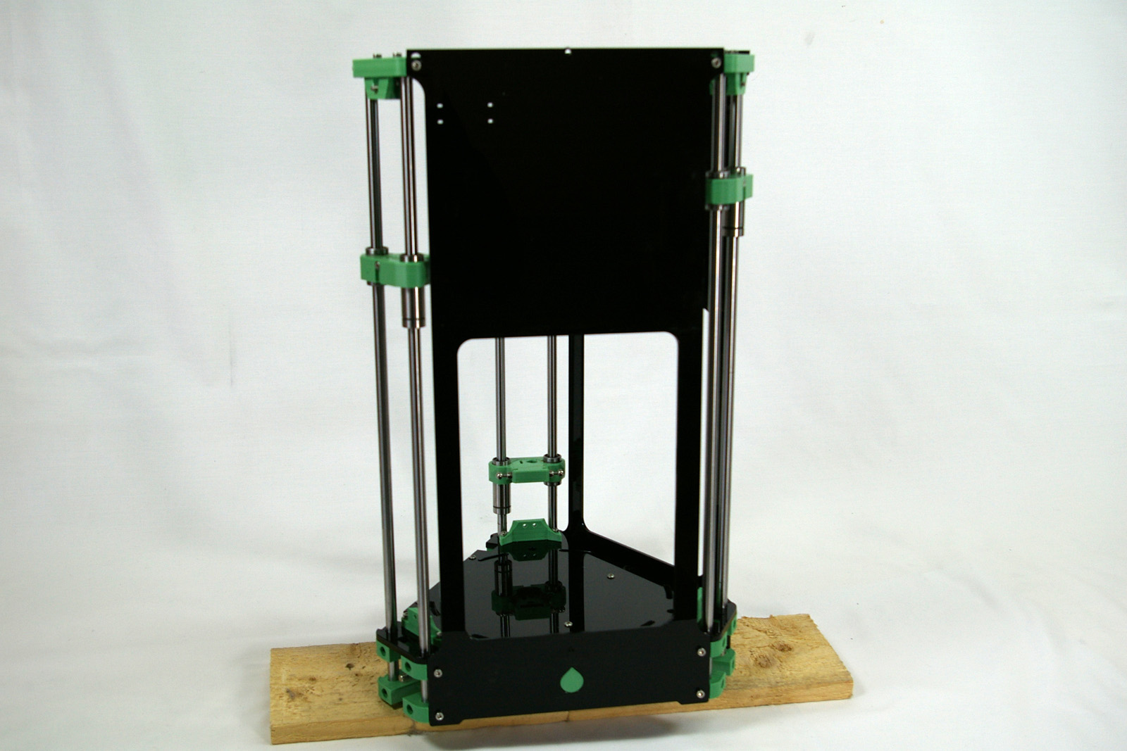
| With both in place, your printer will look like this. The connectors on the Duet electronics are facing the camera out of the open side. The panel with the microswitch is on the left. The panel with the spigot is on the right. | 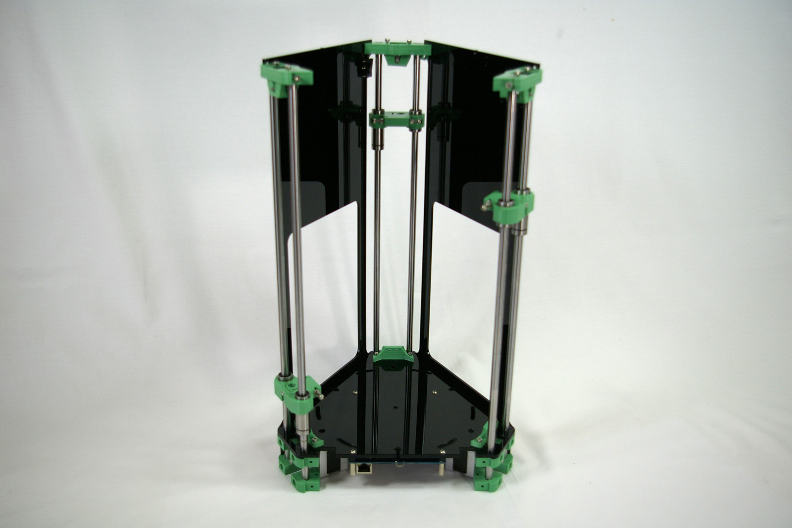 |
Connecting Rods
The connecting rods connect the carriage to the effector, translating the movement of the carriage into the movement of the nozzle. You will need the following parts:
| # | Component | Qty | Type | |
| 1232.1 | Rod | 2 | Laser cut | 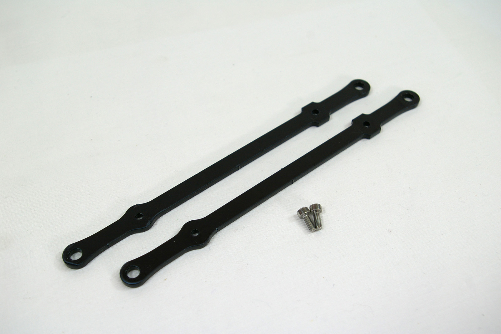 |
| 111 | M3x8mm cap head screw | 2 | Fastener |
Assembling a Connecting Rod
| The connecting rods come in a set, and are connected together to protect them during packing and transit. | 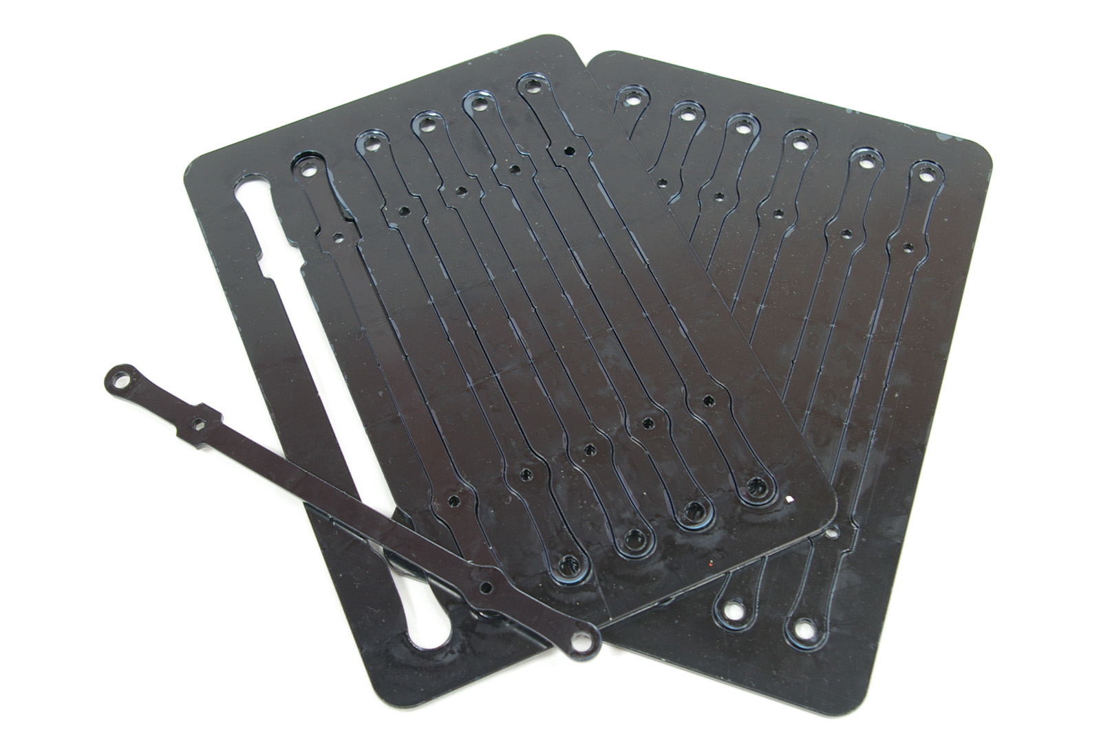 |
| Remove the protective covering from both sides of the acrylic. | 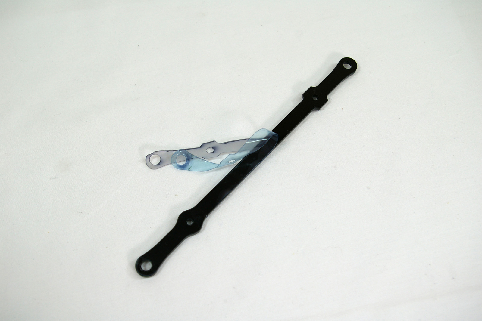 |
| Each rod has a hexagonal and a round hole. The M3x8mm cap head screw should pass through the hexagonal hole, and self-tap into the round hole. | 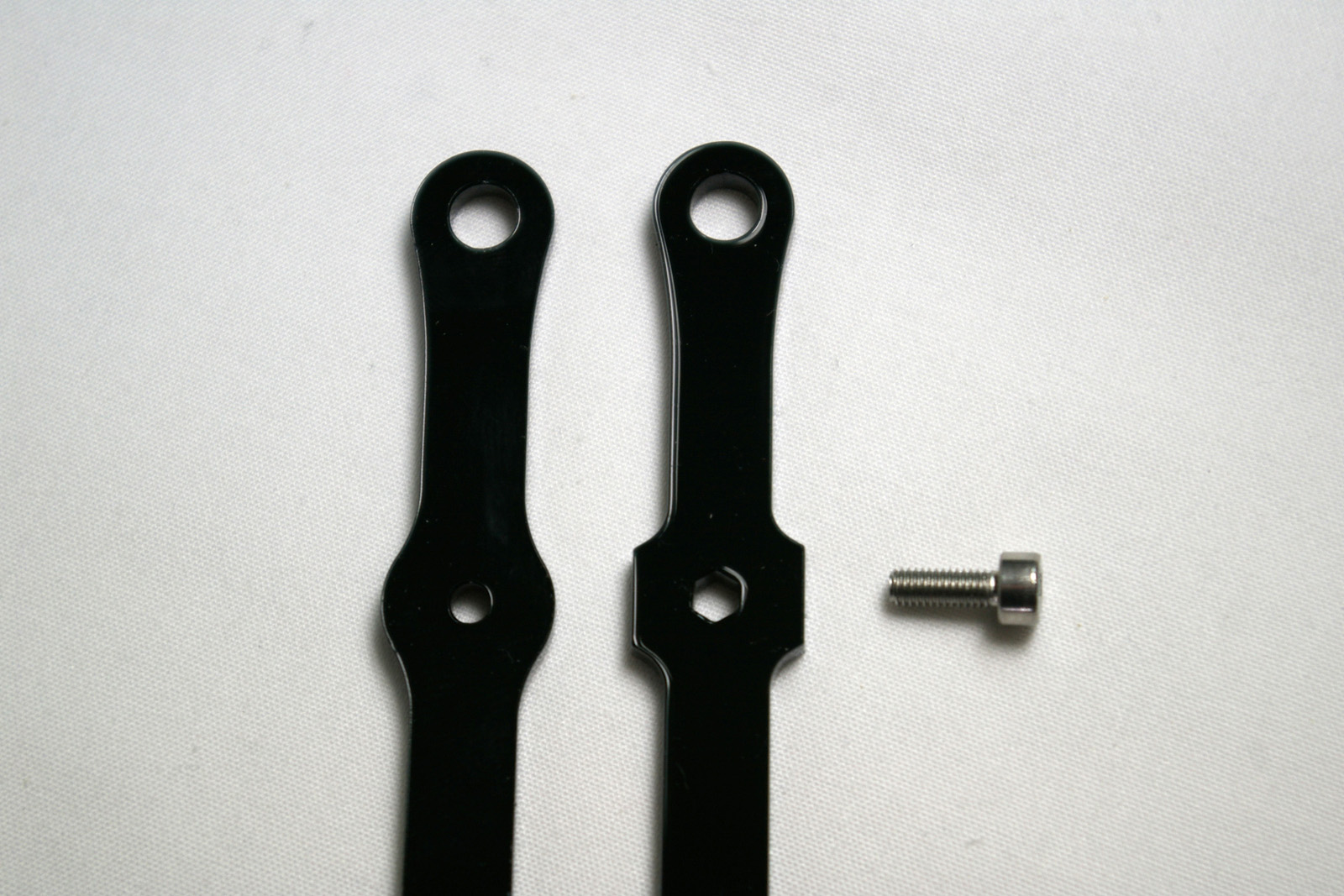 |
| Lasercutting creates an angled cut on the edge of the cut parts. This produces holes with differing diameters on each side of the part. The rods should be paired and arranged such that the angle is mirrored, as shown. Another way to check is that, on the flat faces of the part, one will have a sharper edges than the other. Put the sharper-edged faces together. | 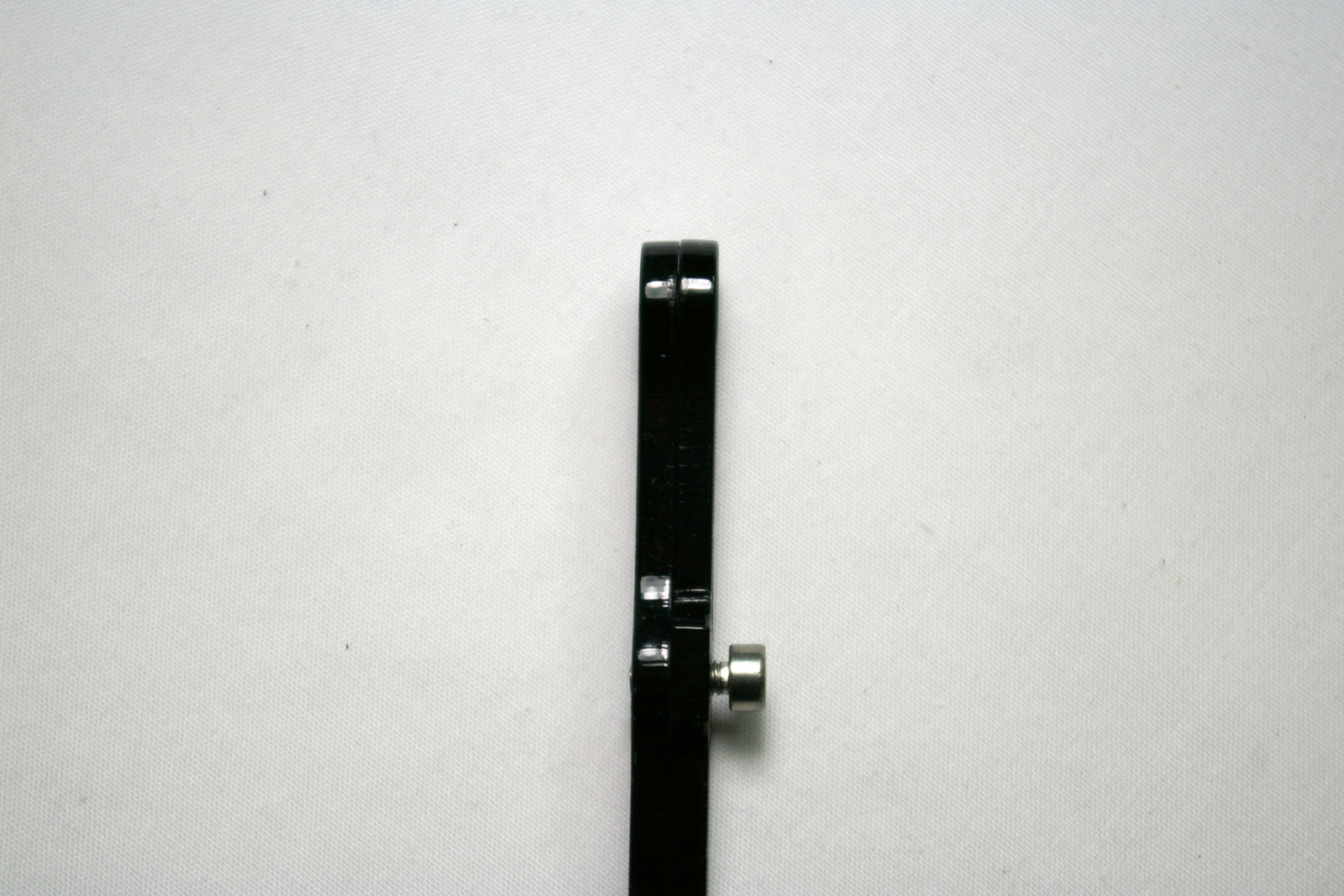 |
| Only screw the M3x8mm cap head screw so it is level with the back of the rod. This will allow it to slip onto the steel ball of the carriage without stressing the acrylic. | 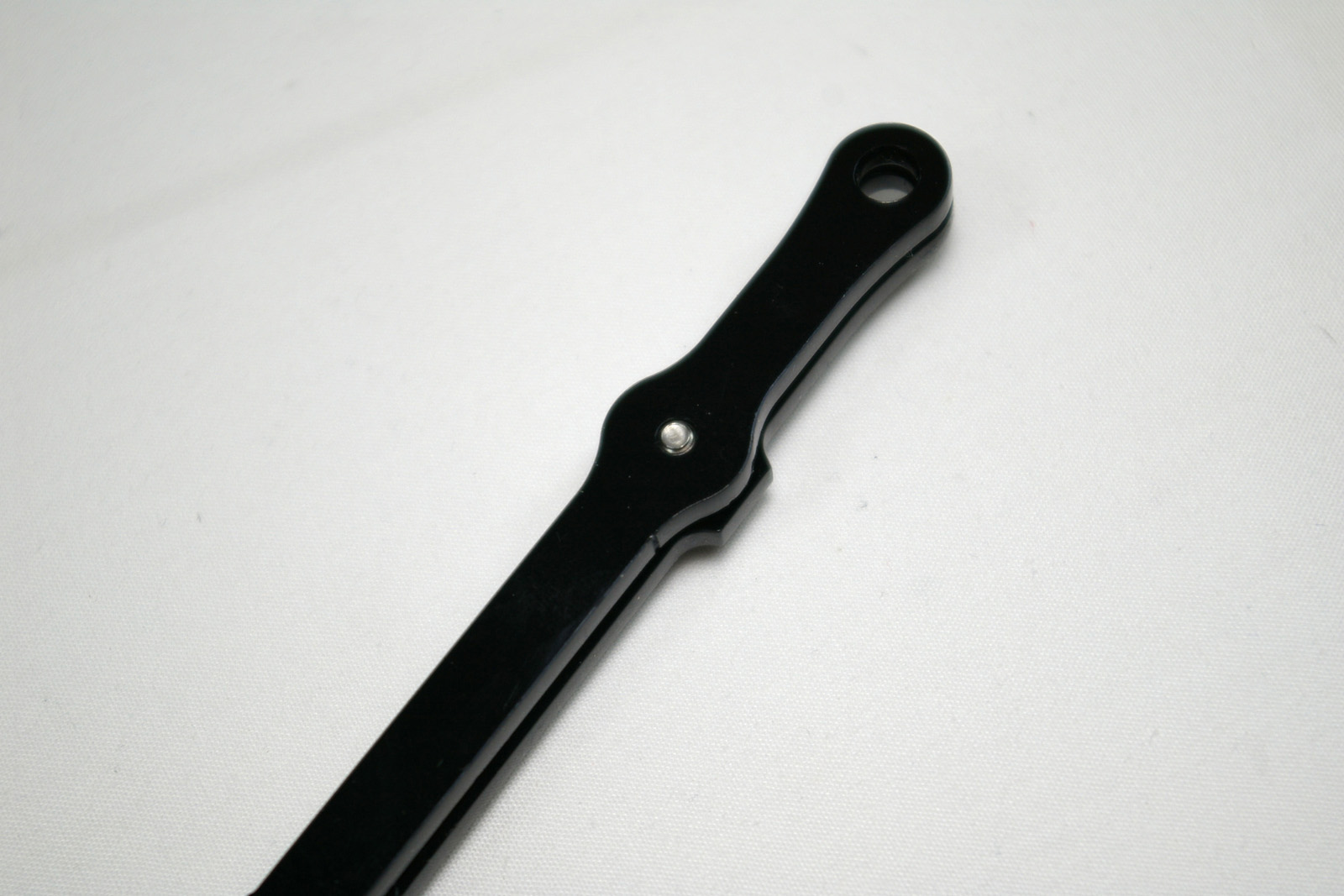 |
| Screw the second M3x8mm cap head screw through the hex hole, and into the round hole, at the other end of the rod. Again, don’t screw it all the way in. | 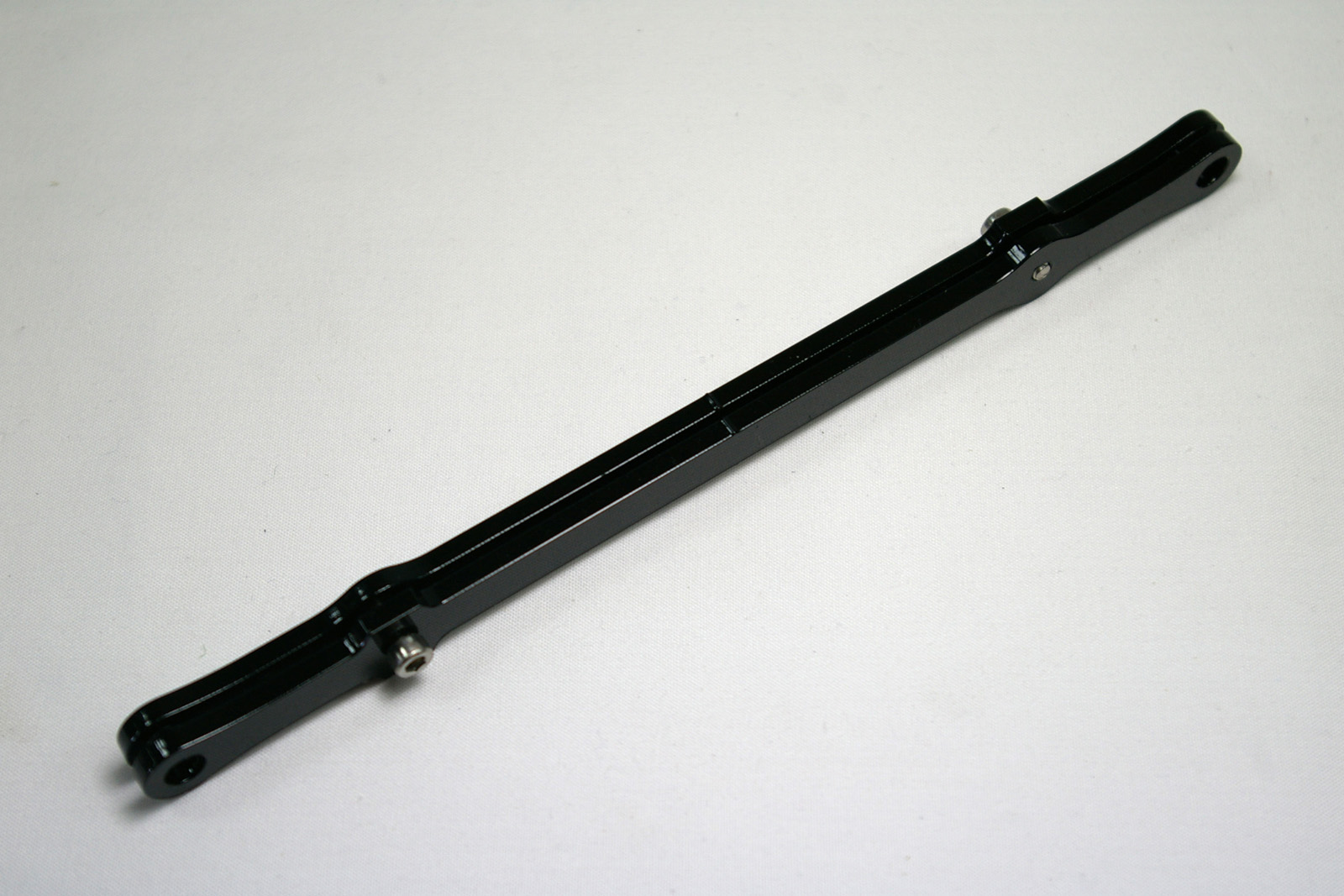 |
Repeat and Connect to the Carriages
| Make a further five connecting rod pairs and set them asside. They will be fitted later. | 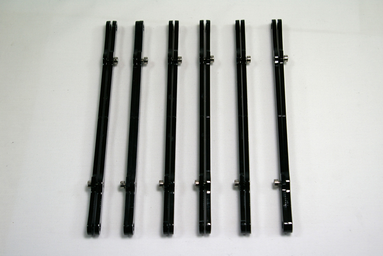 |
Back – Tower Assembly Next – Effector Assembly