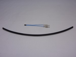
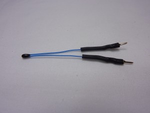
| Bend the thermistor bead at 90 degrees to the wire. |
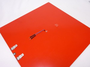 |
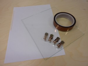
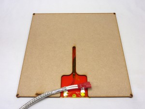
| The thermistor bead fits into the central hole in the heated bed PCB. Secure it in place with some Kapton tape, with the legs of the thermistor pointing towards the PCB contacts. |
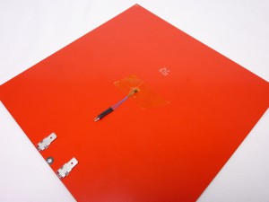 |
| Make sure the thermistor protrudes through the hole in the PCB a little. It will then have good contact with the aluminium heat spreader, and temperature readings will be more accurate. |
 |
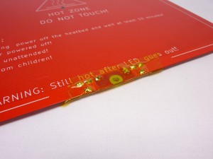
| It’s a good idea to put a piece of Kapton tape over the bed contacts, so you cannot inadvertently short circuit the bed. |
 |
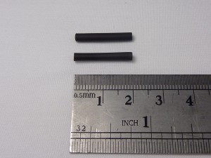
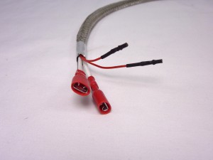
| Put heatshrink on the female crimps of the two smaller wires of the wiring loom, if there is none. Covering any exposed metal, but leave the hole in the end of the crimp clear. These wires connect to the thermistor and have to be insulated from each other, and any other part of the heated bed, or you will get incorrect temperature readings. |
 |
| Connect the wiring loom to the thermistor. The thermistor has no polarity, so it doesn’t matter which way around you connect them. The thermistor wires need to sit in the slot of the MDF bed insulator. Hold It in place with a piece of Kapton tape. Put this over the joins in the thermistor wires; it’s extra insulation in case there is metal poking through, that could come in contact with the metal tape, which is fitted in the next step.This picture shows our Ormerod bed insulator, but the process is identical for Mendel. |
 |
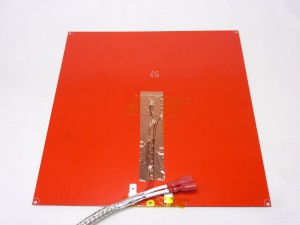
| Tape the wires in place with the metal tape, checking the wires sit between the MDF bed insulator. This shields the thermistor wire from ElectroMagnetic Interference (EMI). |
 |
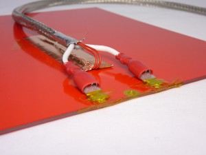
| Push the bed wiring loom crimps onto the tabs on the heated bed. Make sure they are pushed fully on. The bed has no polarity, so they can go on either way around. The wires will be closer to the bed if you put the flat side of the crimp towards the bed, as shown. |
 |
CAUTION!
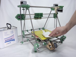
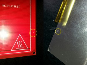
Wipe the aluminium heat spreader with a paper towel, to remove any metal swarf, and carefully check it for damage, burrs or projections before final assembly. Any scrapes or sharp protrusions from the aluminium heat spreader may scratch the PCB, and short circuit through the aluminium heat spreader, which may result in damage to the electronics. |
 |
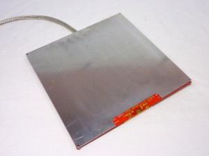
| Line up the aluminium heat spreader with the PCB, making sure that it doesn’t touch the contacts. |
 |
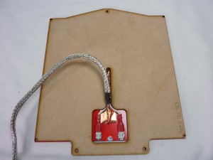
| Turn the bed over, and put the MDF bed insulator in place. |
 |
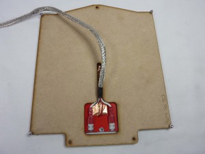
| Now assemble the heated bed by putting M3x12mm cap head screws through the four corners of the bed. The order should be aluminium head spread, PCB, MDF, M3 washer, M3 nyloc nut. |
 |
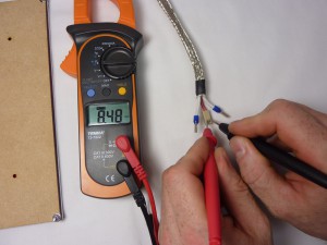
| Test the thermistor wiring at the end of the wiring loom; the resistance should be around 10k ohms. It was a warm day when we took this picture, around 28C, so the reading is lower, at 8.48k ohms. Remember that you have a resistance, which will become apparent with a wrong value if you hold both wires in your fingers… |
 |
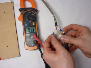
| Test the heated bed power wires are making a good connection by testing the resistance. This measures the resistance of the heated bed, and it should be around 1.3 ohms. You may need to wait for a few seconds for the figure to stabilise. Make sure you have a good battery in your multimeter and check that when you short its leads it reads 0 ohms, or your reading may be inaccurate. |
 |
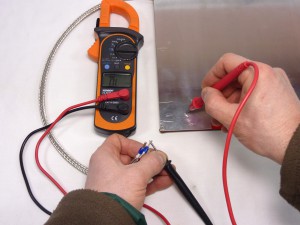
| Finally, test there is NO continuity (i.e. infinite resistance) between the aluminium heat spreader and the contacts of the heated bed. If there is continuity, there is a connection between them somewhere, and possibly the heated bed PCB has been damaged. See the earlier warning in red in this section. |
 |
| The completed heated bed assembly. |
 |
