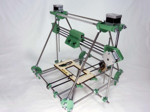
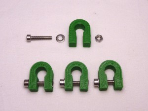
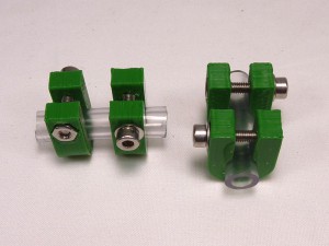
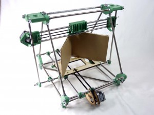
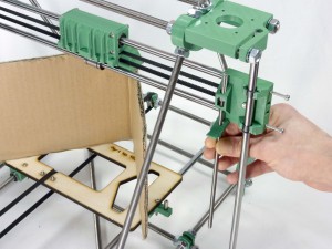
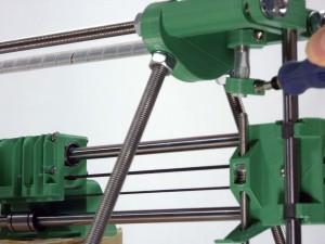
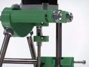
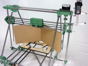
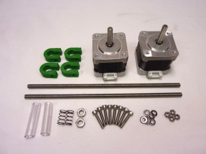
| Undo the U-clips that hold the bottom of the Z-axis rods. Only undo the outside nuts – the inside ones need to stay positioned to relocate the rods when you do things up again.NEEDS PIC |
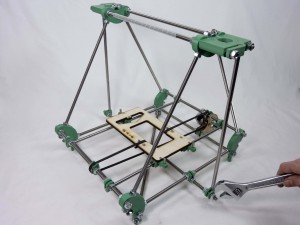 |
| Undo the M8 nuts that retain to tops of the rods. |
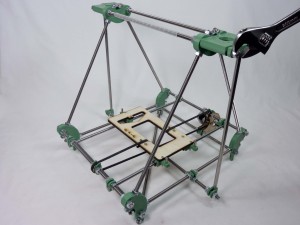 |
| Slide the rods upwards so they are sticking out the top. |
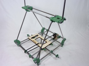 |
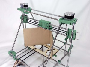
| Push the Z-axis rods down through the Igus bearings in the ends of the X axis. When looking at the front of the machine, the X motor should be facing you on the right hand side. |
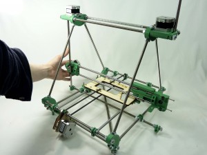 |
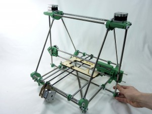
| Put one Z rod back in its retaining bottom U clip. Adjust the width of the X axis as necessary using the screws in the X idler. Slide them back and forth on the X rods until everything fits, then put the other Z rod back in its U clip. |
 |
| Slide the X axis to the top of its travel, and get the gaps between its ends right there. (This will be a distance that cannot be adjusted.) Gently tighten the two screws projecting from the X-axis idler end until they touch the ends of their rods. Don’t over-tighten them, as that will bend the Z rods. |
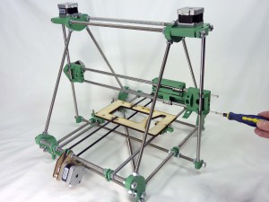 |
| Now slide the X axis back down again, checking that it moves completely smoothly. It may bind for two reasons. First, the X axis may be tilted (like trying to put a drawer in a chest-of-drawers at a slight angle). This doesn’t matter – get it more level and try again. Second, the gap at the bottom of the Z rods may not be quite the same as that at the top. This does matter, and needs to be fixed. To get the bottom Z-rod gap right, carefully move the U clips by undoing and doing up the nuts either side of them. Do this symmetrically. That is to say, if you move the inner nut on the right three-quarters of a turn inwards, do exactly the same with the corresponding nut on the left. It helps to mark one flat on the nuts with a felt-tipped pen so you can keep track of turns. |
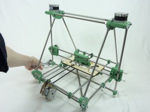 |
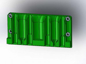
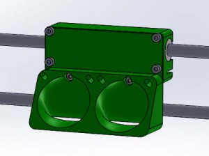
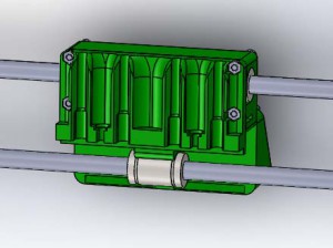
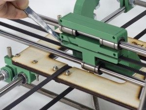
| Keep sliding the X axis up and down the rods, and make small symmetrical adjustments as above until it runs completely smoothly. When you’re happy with the movement, Fit the X belt. Insert one free end into the slot in the right end of the X carriage, so that it locks with the teeth of the small length of belt. It should be placed as far into the slot as possible, so that the end touches the edge of the narrow gap in the centre of the carriage. |
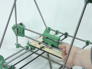 |
| Then feed the belt into the X end Idler and around the small bearing and back through the carriage. There is a mistake on this photo. the X idler cover is missing but should be present on yours. |
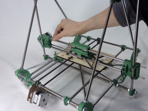 |
| Continue around the motor pulley and back into the slot on the X carriage as shown. e. |
 |
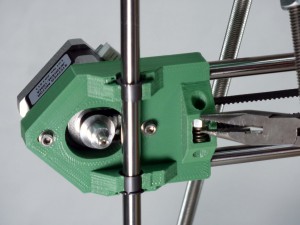
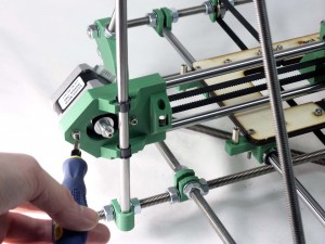
| .Adjust the tension of the belt by loosening the X motor mounting screws, pull the motor back from the centre of the printer, then tighten the X motor mounting screws to hold the belt tight. The axis should move smoothly when pushed by hand, and the belt should be tight enough to make a just-audibly low note if you pluck it on it’s longest stretch.If you cannot get the belt tight enough, then you will need to adjust the belt from the carriage |
 |
