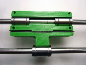
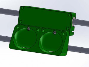
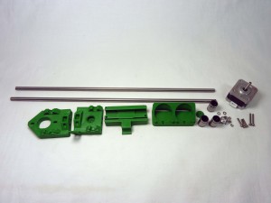
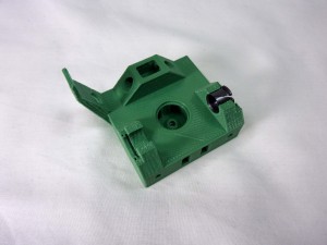
| Start by fitting the Igus bushings into the x ends. These bushings need to allow the Z smooth rods to slide easily but without much slack. In order to achieve this, you will need to fit an Igus bushing into position and slide a smooth rod through it. |
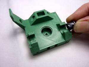 |
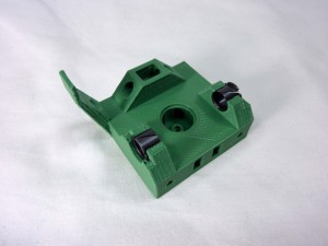
| The bushings can be curled up slightly to fit in downwards. The rims are retained by slots in the 3D-printed parts. Do not attempt to put the bushing in with the smooth rod running through them – this will break the printed part. Put the bushing in on their own, then run the rod through afterwards to check them when they are in place. |
 |
| If the fit is too tight, remove the igus bushing, then remove a small amount of material from the X end. Either use the half-round file to remove material, or clamp a 9mm drill in a vice and run the X end up and down it by hand. Take care – it’s better to remove too little and to have to repeat the procedure, than to remove too much irrecoverably. |
 |
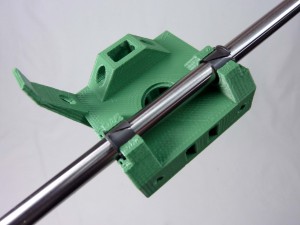
| Try the smooth rod through the bushing again. Repeat this procedure for all four bushing positions. |
 |
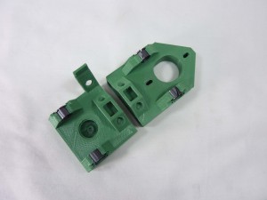
| Repeat for the other X End. |
 |
| Take one M3x16 cap screw and insert it through the hole in the centre of the part as shown. No washer is needed.(The bushings are missing some of the following photos, but they should be left in place). |
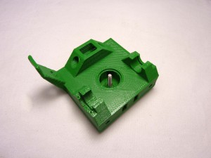 |
| Then insert this assembly through the 623 idler bearing. |
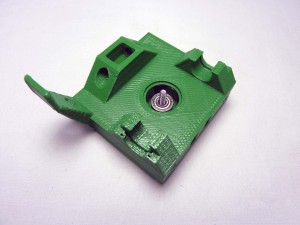 |
| Insert the X idler cover onto the cap screw… |
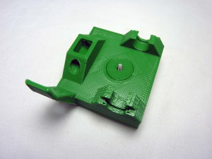 |
| …and secure with an m3 nut. |
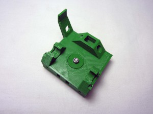 |
| Next insert two M3 nuts into the slots on the back of the idler bracket. These are intentionally a tight fit, so you may need to use a long-nosed pliers in order to grip them. The nuts should go in sufficiently far that the holes of the M3 nuts line up with the small holes in the end of the idler bracket. |
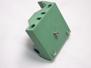 |
| Insert 2 M3x25 cap screws through each of the two holes in the end of the X idler and into the nut. |
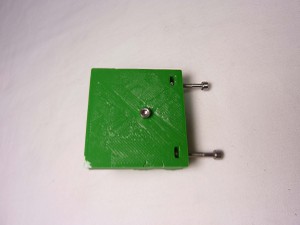 |
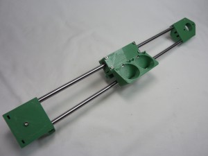
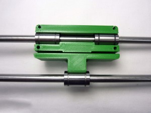
| Next begin to assemble the axis. Take the 426mm smooth rods and insert these into the large holes in the end of the X idler bracket. Then proceed to slide the linear bearings onto the smooth rods. Note the orientation of the bearings, when looking at the top/complex side of the idler bracket, two bearings go on the top bar with the one remaining bearing on the bottom bar as shown |
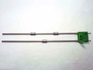 |
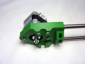
| Ensure the rods are completely inserted into the X idler bracket, then insert the free end of the rods into the X motor bracket |
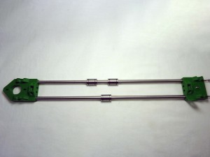 |
