Goal
| By the end of this section, your Mendel 3 should be mechanically and electrically complete, and ready for commissioning. |
 |
Wiring the printer
CAUTION: Never plug in or unplug motors or heaters when the power is on or the USB is plugged in.
Especially with the motors, you risk damaging the motor driver chip, and rendering the whole Duet board useless. This includes unplugging the motor end of the loom, too. A good rule is ALWAYS to turn off the power and to unplug the USB when connecting or disconnecting ANYTHING from the board.
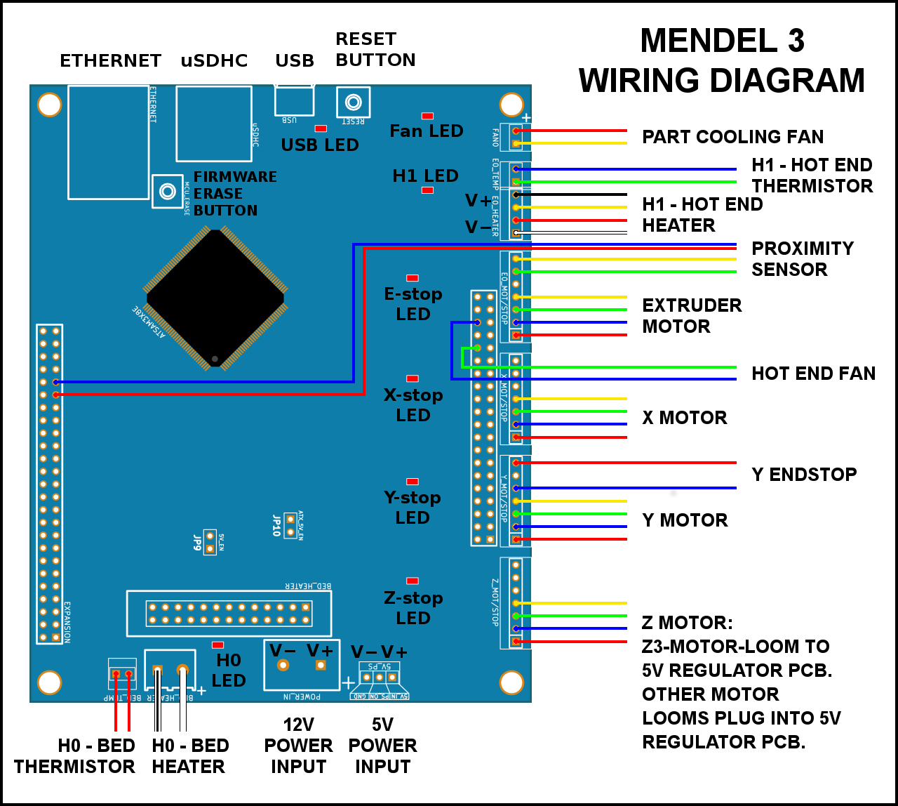
Wiring diagram
The instructions below show the fitting of the wiring. If in doubt, refer to this wiring diagram.
Fitting the wiring looms
RepRapPro Mendel 3 printer kits are supplied with pre-assembled wiring looms. It’s easiest to fit these at the terminating end, route them back to the Duet, before plugging them in, and finally tidying up the wiring. Labelling the wires will also help!
Heated bed wiring
| Connect the heated bed loom at the Duet end. The white wires can go into the screw terminal either way around; polarity is not important on the heated bed. Make sure the ferrules are fully inserted in the screw terminals, and the screw terminals are firmly tightened. The thin red wires connect to the pins next to the screw terminal, and are for the bed thermistor. The silver tape goes in the notch in the enclosure perimeter, and provides the earth for the loom braiding; make sure that the perimeter doesn’t cut through the braiding, and damage the wires, which can cause a short circuit. |
 |
| The other end of the loom should already be attached to the bed. Check that the routing runs in a loop under the bed, and doesn’t drop below the Y sled at any point, or it may catch on the Y axis. There is a hole on the edge of the lasercut bed insulator; thread a cable tie through this, and use it to secure the loom to the bed as shown. |
 |
| The main part of the loom should form a large loop. It needs to bend along the length of the loop, but without hinging in one place – if it does, the wires will fatigue over time, and eventually break. Slide the Y carriage back and forth, making sure the bed loom moves smoothly along the full range of the Y axis. |
 |
| Note: It is very important that the bed loom is free to move. If it catches on anything, either limit the movement of the bed loom at that point (cable tie the loom in place), or protect it (cover the object, or loom, with Kapton tape, or something similar, so it can slide smoothly over it). Check that the cable is free to move, and in good condition, regularly. |
|
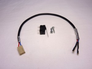
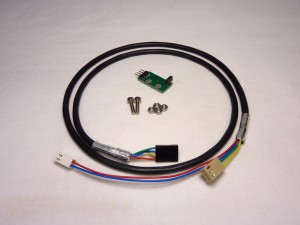
Y-endstop loom
| # |
Component |
Qty |
Type |
| 1038 |
Endstop loom – 295mm |
1 |
Wiring |
| 185 |
Microswitch |
1 |
Electronics |
| 918 |
#4 round head screw |
2 |
Fastener |
|
 |
| Drill the mounting holes of the switch out with a 3mm drill. This allows the supplied #4 screws to fit through easily. |
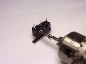 |
| Fit the microswitch to the tabbed Y-rod-clamp, using the #4 round head screws. |
 |
| Check the Y-carriage makes contact with the endstop. Move it to the end, and as it touches the endstop, the microswitch should make a small ‘click’. |
 |
| Connect the Y endstop wiring to the OUTER two pins of the microswitch. If they are a little loose, and won’t stay on, use a pair of pliers to lightly crush the crimp on the loom, to make the fit tighter.We only use a microswitch endstop for the y-axis; the x- and z- axis use the proximity sensor to sense where the end of the axis is (the ‘home’ position). |
 |
Motor wiring looms
| # |
Component |
Qty |
Type |
| 1041 |
x motor loom – 900mm |
1 |
Wiring |
| 1042 |
y motor loom – 500mm |
1 |
Wiring |
| 1042 |
z1 motor loom – 500mm |
1 |
Wiring |
| 1043 |
z2 motor loom – 800mm |
1 |
Wiring |
| 793 |
z3 motor loom – 50mm |
1 |
Wiring |
| 1040 |
Extruder motor loom – 930mm |
1 |
Wiring |
| 579 |
motor-shield |
5 |
Laser cut |
| 520 |
M3x35mm cap head screw |
5 |
Fastener |
|
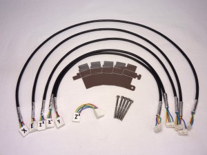 |
| Take the six motor looms. Check the wiring order of the wires in the housings; if they have been assembled incorrectly, the motor will not run correctly. It’s a really good idea to mark the motor looms, this will make it easier to connect them to the Duet. From longest to shortest, they are Extruder,X, Z2, Z1, Y and Z3. Z1 and Y are the same length. |
|
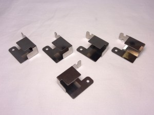
| Take the five motor shields. Bend the first one, at 90 degrees along the score lines, as shown. You need four left-handed ones, and one right-handed one. Compare the one you have bent to the picture, and bend the other four appropriately. Try not to unbend them; they will fatigue and break after a couple of attempts. |
 |
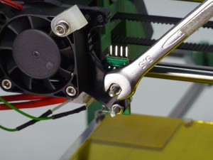
| For each of the motors, you will need to remove one of the screws, to attach the shielding. Start with the Y motor, and remove the screw shown with a cross head screwdriver. |
 |
| Take the Y motor loom (the shortest except for the very short z3-motor-loom), and connect it to the motor. Put a bend in the wire as shown. |
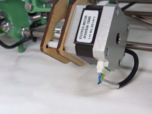 |
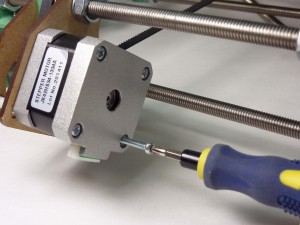
| Take the motor shield (the one ‘right-handed’ shield), and place it over the connector. Secure with an M3x35mm cap head screw. |
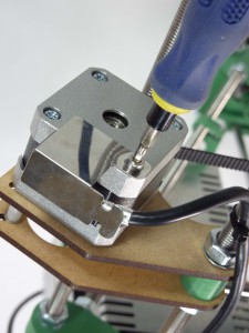 |
| Finally, take a cable tie and put it around the loom, so the silver tape covering the end of the loom is trapped in the cable tie, and makes good contact with the shielding. This ensures the motor shielding is continuous, and very little electrical noise should escape. |
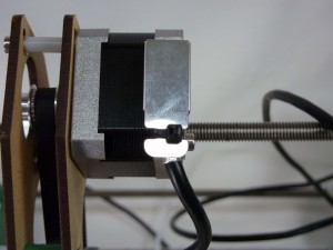 |
| Connect the looms to the other motors in a similar fashion. The wiring is highlighted in pink in each case The Z motor closest to the Duet uses z1-motor-loom, while the one next to the extruder uses the z2-motor-loom. |
 |
| The extruder motor uses the next longest motor loom. It goes through the gap between the extruder motor and the frame. |
 |
| The X motor loom is the next longest, only slightly shorter than E. |
 |
| Loosely hold the Z, X and extruder looms in place with a cable tie. |
 |
Proximity sensor and loom
| # |
Component |
Qty |
Type |
| 1039 |
Proximity loom – 1025mm |
1 |
Wiring |
| 545 |
Proximity sensor |
1 |
Electronics |
| 242 |
M3x16mm cap head screw |
2 |
Fastener |
| 258 |
M3 nut |
4 |
Fastener |
|
 |
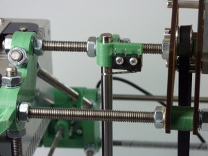
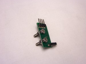
| The proximity sensor is a small PCB, with four pins on the end of the board. Make sure the sensor itself, the black part at the other end from the pins, is standing perpendicular to the board; they can get bent over in transit. Push the two M3x16mm cap head screws through the board, and put an M3 nut on each, on the back. |
 |
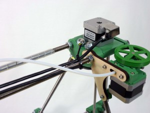
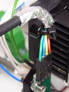
| Attach the proximity sensor to the X carriage to the right of the hot end, through the two holes in the acrylic. Hold it in place with the other two M3 nuts. The first M3 nuts space the PCB away from the acrylic. The sensor should be on the side facing the X smooth rods. |
 |
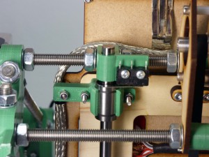
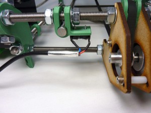
| Connect the proximity sensor loom. NOTE: the sensor has a polarity; the order of the wires is VERY important. It should be as the picture, from left to right: green, blue, yellow, red. Red should be closest to the heatsink. The acrylic heatsink spacer has two holes in it, for a cable tie to hold the loom. Secure the loom as shown, making sure the loom is fully engaged on the sensor pins. Make sure the cable tie runs through both holes in the acrylic, if you only use one the wire can twist and pull the cable loose. |
 |
Hot end and fan looms
| # |
Component |
Qty |
Type |
| 1035 |
Hot end loom 850mm |
1 |
Wiring |
| 1037 |
Fan loom 850mm |
1 |
Wiring |
|
Picture to come |
| Connect the hot end and fan looms. The six-wire loom connects to the hot end plug, the four wire loom connects to the fans.(The proximity loom is not fitted in this photo, but should be on your machine) |
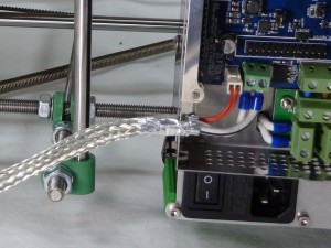
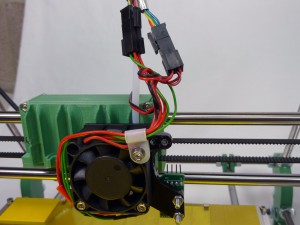 |
| Cable tie the three looms(Hot end, fan and proximity) to the bowden tube. Ensure the cable tie is on the loom side of the connectors rather than the hot end side. This provides strain relief for the wires. (The proximity loom is not fitted in this photo, but should be on your machine) |
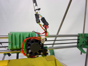 |
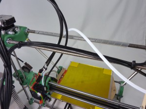
| The hot end looms run between the top threaded rods of the machine and then cable ties to the threaded rod of the frame triangle closest to the electronics…. |
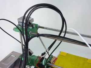 |
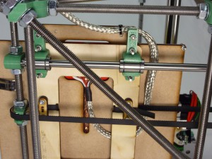
| Cable tie the hot end looms, and the motor wires, lightly to the frame. Leave a generous loop (you will adjust this in the next steps) to allow the X carriage to move back and forth, and up and down. |
 |
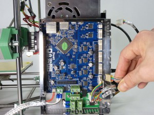
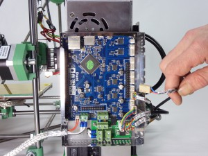
Connecting the looms to the Duet
For each axis, the Duet has 7 pins; 4 for the motor, three for the endstop (when needed). Check with the wiring diagram at the top of the page the orientation of the motor wire, and the exact pins it plugs into.
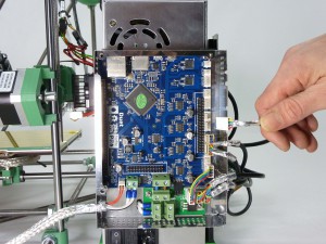
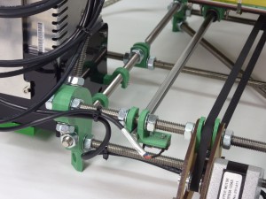
| The Z axis plugs in on the lowest pins on the Duet. On Mendel 3, the z-axis is a special case; it has two motors. The 5V regulator board has special pins. Connect the z3-motor-loom (the shortest) as shown. |
 |
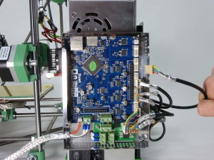
| Connect z2-motor-loom to the the plug closest to the enclosure-perimeter. |
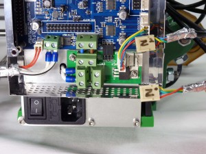 |
| z1-motor-loom plugs in in the middle. |
 |
| This shows the Z motor looms plugged in. |
 |
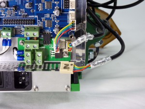
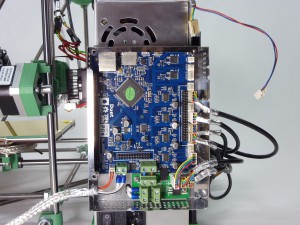
| We’ll be plugging in the rest of the motors, in order, from bottom to top. Next is the Y axis motor loom. |
|
| Then the Y endstop |
 |
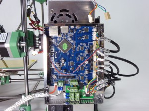
| Then the X axis motor loom. |
 |
| Then the extruder motor loom. |
 |
| The proximity sensor loom has two connectors. The short wires plug in to the extruder endstop pins, which are above the Extruder motor loom. The longer wires reach across the board, and plug into two pins in the expansion header. Check the wiring diagram at the top of the page to see exactly which pins. |
 |
| The hot end loom also has two connectors, one with four wires and on with two. It is VERY important that these are connected correctly, or you may damage the Duet. They connect ABOVE the Extruder endstop loom. Again, check with the wiring diagram above to get the correct pins. |
 |
Pay particular attention when connecting the hot end heater and hot end thermistor connectors. If you put them in the wrong place, 12V (from the heater or fans) can run down the 3.3V line of the thermistor, and will immediately destroy the main processor chip. We regard this mistake as a user error, and is NOT covered by the warranty. Check your wiring! |
| The hot end fan loom also has two connectors. Again, check with the wiring diagram above to get the correct pins. NOTE: the picture shows the red and yellow wires for the part cooling fan the wrong way around. The red wire (+12V) should be above the yellow (ground). The wiring diagram, at the beginning of this page, is correct. |
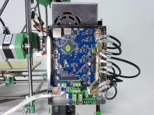 |
| The cover in place. All the wires should sit in the slots in the enclosure perimeter, and the cover keeps them in contact for good grounding, as well as supporting the wires. You may want to leave the cover off (again), until after the commissioning stage (the next page of the instructions), as it is useful to be able to access the Duet board, ie to press ‘reset’, or check your wiring, during commissioning. |
 |
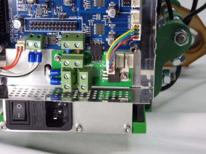
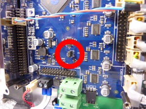
IMPORTANT: 5V JUMPER!
| Fit the 2-way PCB jumper (a small, black, jumper block) on the two pins in the centre of the board, labelled ‘J10’ and ‘ATX_5V_EN’. Without this, the Duet board will not be supplied with power without the USB connected! |
 |
Wire routing
| Use a couple of cable ties to hold the motor wires to the edge of the frame. |
 |
| Use a couple more to hold all the wires at the top of the frame. |
 |
| Test the movement of the x-axis along the full range of motion. Check the wires do not kink, or get caught. |
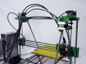 |
| At the far end, check the wires don’t get caught. |
|
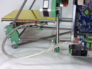
| Attach the Y endstop and Y motor looms in place with a couple of cable ties. Make sure the bed can pass by them, without hitting them. |
 |
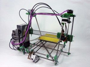
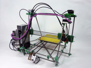
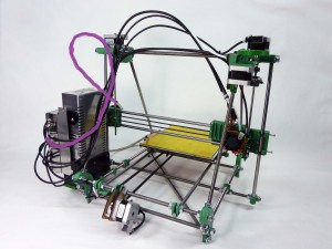
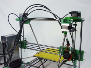
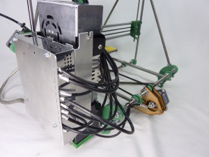
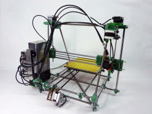
| The finished wiring. |
 |
Wiring finished
| The printer, showing the wiring complete. |
|


