Duet electronics enclosure
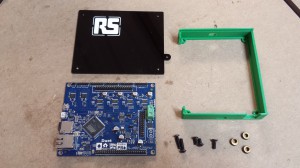
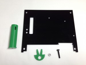
Mount the electronics enclosure using the following parts:
| Component |
Type |
Quantity |
| Duet-enclosure |
Printed |
1 |
| Duet-enclosure-base |
Lasercut |
1 |
| M4x16mm button head screw |
Fastener |
2 |
| M4x8mm button head screw |
Fastener |
2 |
| M4x16mm countersunk socket screw |
Fastener |
1 |
| M4 T-nut (not shown) |
Fastener |
3 |
| Spacer |
Lasercut |
3 |
|
 |
NOTE: Some early Duet boards were shipped with 3.5mm diameter mounting holes. These should be 4.2mm in diameter. If you have one of the affected Duet boards, it is ok to enlarge the holes with a 4-4.5mm drill.
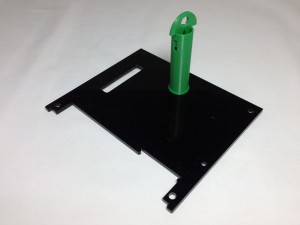
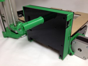
| Mount the Duet electronics board in the Duet-enclosure printed part, and put the lasercut Duet-enclosure-base on the back. The two M4x8mm button head screws go in the top mounting holes, and self-tap into the Duet-enclosure-base. |
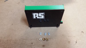 |
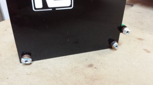
| The two M4x16mm button head screws go in the bottom two mounting holes, through the cover, and have a spacer between the cover and the T-nut. The M4x16mm countersunk screw goes through the lug on the side, again with a spacer and T-nut on it. |
 |
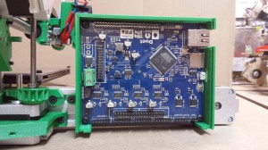
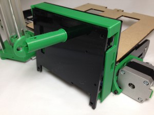
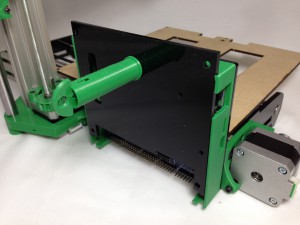
| Mount the Duet enclosure on the end of the Y axis extrusion, near the Y motor. IMPORTANT – Make sure the Hot end carriage can pass by it (it will be close), or the X axis will not ‘home’ properly. You can move the X-carriage by hand to test. |
 |
Enclosure rear cover
The rear cover needs the following parts:
| Component |
Type |
Quantity |
| Duet-enclosure-lid |
Lasercut |
1 |
| spool-spigot |
Printed |
1 |
| spool-clip |
Printed |
1 |
| M3x16mm cap head screw |
Fastener |
1 |
| M3 nut |
Fastener |
1 |
|
 |
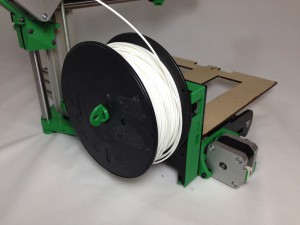
| Drop the M3x16mm cap head screw down the spool-spigot, so the thread comes out of the hole in the end. Secure to the Duet-enclosure-lid, through the hole shown, with the M3 nut. The spool clip pushes into the end of the spool-spigot. |
 |
| You may need to flatten the two earthing springs on the top of the ethernet connection. To mount the rear cover, clip it into the top securing lugs in the printed enclosure by sliding it up from below. |
 |
| Slide the cover up, while pushing it flat into the frame, so it rests on the lip of the frame. |
 |
| Slide the cover down, so the bottom of the cover is secured by the lugs on the printed part. Removal is the reverse of installation. |
 |
| Pull out the spool-clip, slide on the filament spool, and replace the spool-clip. You will need to remove the cover to connect the wiring. |
 |
For the moment, remove the spool and rear cover. It will get in the way while the rest of the printer is built.
ATX power PCB
| Component |
Type |
Quantity |
| ATX power PCB |
Electronics |
1 |
| ATX power PCB enclosure |
Printed |
1 |
| M4x16mm button head screw |
Fastener |
2 |
| M4 T-nut |
Fastener |
2 |
| Spacer |
Lasercut |
2 |
|
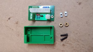 |
| Mount the ATX Power PCB in a similar way to the Duet. The two M4x16mm button head screws go in the diagonal two mounting holes, through the enclosure, and have a spacer between the enclosure and the T-nut. |
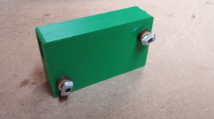 |
| Mount the ATX power PCB enclosure on the end of the Y axis extrusion, near the Y idler. |
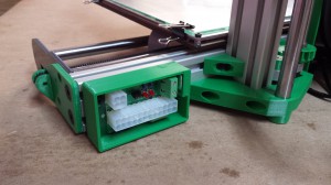 |
| Plug the large 24-way connector and the 4-way connector into the ATX Power PCB. These are keyed, so you can’t put them in the wrong way. Make sure they are pushed in all the way. |
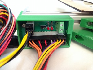 |
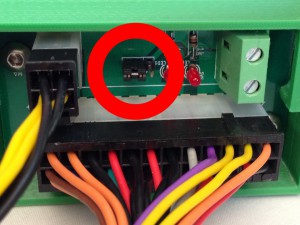
| Make sure that there is a jumper on the pair of pins that are closest to the white 4-way connector, not on the pair that is closest to the LEDs. This controls the ATX power supply unit (PSU) – without the jumper, the PSU will not turn on. |
 |
| Now test the ATX PSU. Plug the PSU into a wall outlet, and turn on. There is a power switch on the back of the PSU; turn this on too. The ATX fan should spin, and the two LEDs on the ATX Power PCB should turn on. You should be able to measure 12V on the screw terminals of the ATX Power PCB. Once tested, turn off and disconnect the PSU. Leave the PSU connected to the wall outlet for a few minutes to discharge any capacitance. |
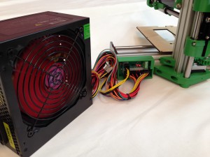 |
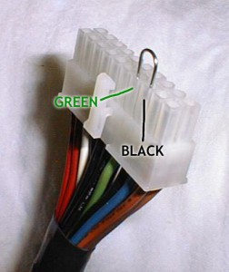
| Problems? If you only get one LED on the ATX power PCB, and the fan does not spin, check the plug connections (step 3, above) and the jumper is in place (step 4, above). If this doesn’t help, check the ATX PSU. Disconnect the PSU from the Power distribution PCB, and put a wire jumper between the green wire and a black (ground) wire. The green wire is the PSU sense wire; if it is shorted to ground, the PSU will turn on. This is what the ATX Power PCB is doing, and what the jumper does on the pins that are on the board. With the wire jumper between the green and black (see attached picture), turn on the PSU. The main fan should start spinning, and you should be able to measure 12V between any yellow and black pair of wires. If not, test with another mains cable, if available. This should diagnose if the problem is with the ATX PSU, or the ATX power PCB. Contact support for further advice. |
 |


