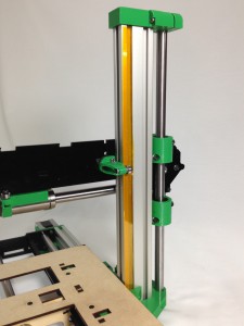
The X axis assembly can now be mounted to the previously assembled ZY assembly.
Z axis leadscrew
First, prepare the Z axis leadscrew, using the following:
| Component |
Type |
Quantity |
| z-gear-driven |
Printed |
1 |
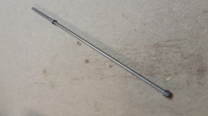
| M5 threaded z-rod |
– |
1 |
| M5 Nut |
Fastener |
3 |
|
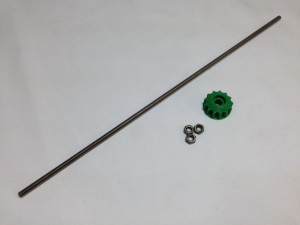 |
| Screw two of the nuts onto one end of the M5 threaded z-rod. Lock one nut against the other right at the end of the rod. Screw the third nut onto the other end of the z-rod. |
 |
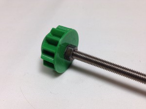
| Push the z-gear-driven onto the locked M5 nuts. The bottom nut of the two should fit into the nut trap in the gear. |
 |
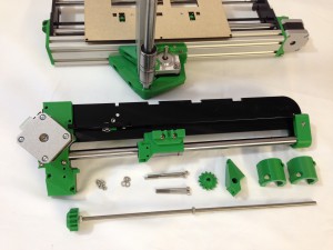
X axis assembly
NOTE: The z-nut-trap printed part has been updated. All red RS kits were supplied with the z-nut-trap as shown in these pictures. All current kits have the nut trap in the printed part, rather than in the x-rib. Assembly of the axis is still the same. If you have a red RS kit, once you are printing, you can print out the part, modify the x-rib, and fit the new version.
Now, the x-axis-assembly can be mounted on the z axis. For this, the following parts are required:
| Component |
Type |
Quantity |
| x-axis-assembly |
Assembled |
1 |
| z-axis-leadscrew |
Assembled |
1 |
| z-bearing-clamp |
Printed |
2 |
| z-nut-trap |
Printed |
1 |
| z-gear |
Printed |
1 |
| M3x50mm cap head screw |
Fastener |
2 |
| M3x40mm cap head screw |
Fastener |
2 |
| M3 Nut |
Fastener |
4 |
| M3 washer |
Fastener |
4 |
|
 |
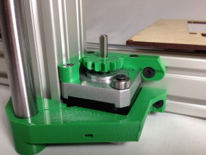
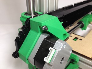
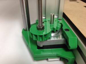
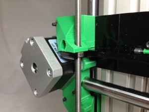
| Press the z-gear onto the z-motor shaft, conical side down. The z-gear has a flat in the hole, that should align with the flat on the motor shaft, which stops the gear rotating on the shaft. The gear should be a tight fit, so make sure you line it up before pushing the gear on the motor shaft. |
 |
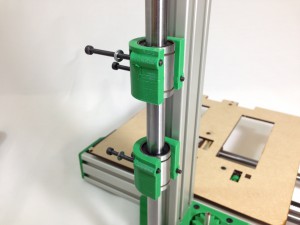
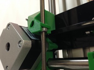
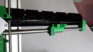
| Slide a z-bearing-clamp onto each z axis linear bearing. Place the two M3x50mm cap head screws in the top mount, and the two M3x40mm cap head screws in the bottom mount, with a washer under each head. |
 |
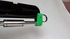
| Take the x-axis-assembly. Hook the z-runner-mount bearing around the z axis aluminium extrusion. |
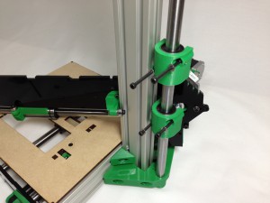 |
| Offer up the x-axis-assembly and push the four z-bearing-mount screws through the X axis. The X axis can now sit at the bottom of the Z axis. |
 |
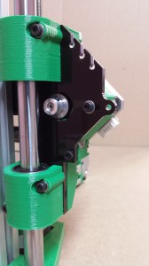
| Use two M3 nuts to secure the bottom z-bearing-mount. Don’t do them up too tight yet. |
 |
| Use a screw to pull an M3 nut into the recessed nut trap, in the z-nut-trap printed part. |
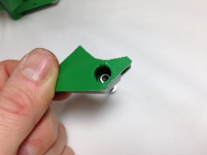 |
| Push the z-nut-trap onto the end of the 50mm cap head screws, add the remaining M3 nut, and do up the screws, but not tight. |
 |
| Now tighten the bearing mount screws. The holes in the bearing clamps are clearance for the M3 screws, so keep moving the axis up and down between turns of each screw. This will let the bearings settle in the right place, and ensure the axis runs smoothly. |
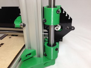 |
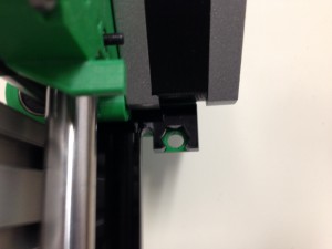
| Check that the hole in the z-nut-trap is central in the x-rib laser cut part – if it is not, the Z leadscrew nut may break the x-rib. This picture is looking up the Z axis from the bottom. |
 |
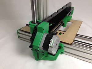
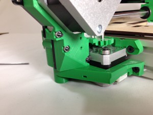
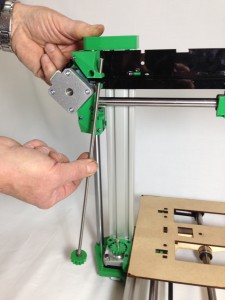
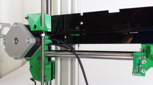
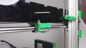
| Lift the X axis to the top of the Z axis, and carefully feed the z-axis-leadscrew assembly up through the z-nut-trap. |
 |
| The z-axis-leadscrew sits on the 623 bearing on the corner of the Z axis motor, engaging with the z-gear on the motor. |
 |
| The x-axis-assembly can now be supported by the loose M5 nut on the z-axis-leadscrew. Gently lower the X axis onto it, being careful to orientate the M5 nut correctly – see picture. |
 |
| RS kits with red plastics have a different design, and the nut trap is in the acrylic x-rib. It fits in the same way. Don’t force it – it will break the nut trap on the x-rib. You can print out the current design z-nut trap and replace the old one, by cutting off the nut trap on the acrylic x-rib. |
 |
X axis drive belt
| Component |
Type |
Quantity |
| 1/4″ MXL Belt (not shown) |
Hardware |
710mm |
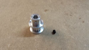
| MXL pulley |
Hardware |
1 |
| M3 grub screw |
Hardware |
1 |
|
 |
| The X axis drive belt can now be fitted. The 1/4″ MXL belt should be accurately cut to 710mm in length. |
|
| Put the pulley on the motor shaft. Remove the motor to do this. The motor shaft has a flat on it; align the grub screw with this, and tighten the grub screw using a 1.5mm Allen key. The pulley needs to sit right on the very end of the motor shaft, as shown in the picture. Don’t tighten the motor mounting screws, so the motor can slide. This allows for belt tension adjustment. |
 |
| Insert the belt through the slot in the x-motor-bracket, around the drive pulley and back out through the second slot. This is quite fiddly; moving the motor back and forth will help feed the belt through, as will rotating the motor pulley. |
 |
| Slide the end of the lower section of belt into the x-carriage. It is easiest to do this with the x-carriage separated from the linear bearing. The end of the belt should be flush with the end of the x-carriage. |
 |
| Twist the top section of belt 180 degrees, and pass it over and around the idler bearing. The smooth side of the belt will be in contact with the bearing. |
 |
| Bring the belt back to the x-carriage and mesh it with the other end of the belt. |
 |
| Push the belt into the x-carriage slot. |
 |
| The linear bearing can now be slid back into the x-carriage. |
 |
| Tighten the belt by sliding the X axis motor. Tighten the motor mounting screws. |
 |
Checking for play in the x axis
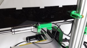
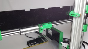
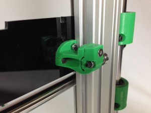
Rotation of the x axis around the z axis is prevented by the bearings on the z-runner-mount, mounted on the x axis. It is important it is held securely, but not overly-tight.
| Current kits use an adjustable z-runner-mount, which can be adjusted to tension the bearing onto the aluminium extrusion. Don’t overtighten this, or movement of the Z axis may be compromised. |
 |
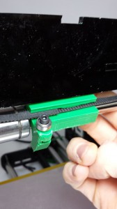
Some customers with the red RS kits, and a non-adjustable z-runner-mount, have reported that it is slightly loose, and causes the end of the x axis to wobble a couple of millimetres. To get printing (and then print yourself a new z-runner-mount), there are a couple of workarounds:
| Using the supplied Kapton tape, put layers around the z-runner-mount bearing until the play is eliminated. Kapton tape is 50 microns (0.05mm) thick. |
|
| Using the supplied Kapton tape, put layers on the aluminium extrusion, between the extrusion and the path of the bearing, until the play is eliminated. It took 3 layers of Kapton on our build of a production printer. |
 |


