
Wiring the printer
CAUTION: Never plug in or unplug motors or heaters from your Duet board when the power is on.
Especially with the motors, you risk damaging the motor driver chip, and rendering the whole Duet board useless.
This includes unplugging the motor end of the loom, too.
A good rule is to ALWAYS turn off the power when connecting or disconnecting ANYTHING from the board.
Especially with the motors, you risk damaging the motor driver chip, and rendering the whole Duet board useless.
This includes unplugging the motor end of the loom, too.
A good rule is to ALWAYS turn off the power when connecting or disconnecting ANYTHING from the board.
| Hot end loom. Length: 930mm |
 |
| Proximity sensor: Attach the proximity sensor to the X carriage to the left of the hot end with 2 x M2.5x5mm cap head screws. Connect loom. NOTE: the sensor has a polarity; the order of the wires is very important. It should be as the picture; blue, black, red (or pink on some looms). Loom length: 960mm |
 |
| Extruder drive motor loom. Length: 720mm |
 |
| X axis motor loom. Length: 440mm |
 |
| Z axis motor loom. Length: 90mm |
 |
| Y axis motor loom. Length: 160mm |
 |
| Y axis endstop: The loom connects to the outer two pins of the microswitch. You will need to bend the top pin upwards to 45 degrees, so the wire doesn’t foul the Y axis belt pulley. Length: 260mm |
 |
NOTE: You may have received the Y axis endstop wires and the Hot End fan wires with a 2-way housing. It should be a 3-way housing on each of these, with the centre connector unused. However, you can remove one crimp from the housing (lift the little tab on the housing and pull out the wire and crimp) and plug it into the board directly; the image below shows we have done this on the hot end fan.
Wiring the Duet
Connect each loom as per the diagram shown:
Pay particular attention when connecting the hot end heater and hot end thermistor connectors. If you put them in the wrong place, 12V can run down the 3.3V line of the thermistor, and will immediately destroy the main processor. We regard this mistake as a user error, and is NOT covered by the warranty. Also take care with the Extruder motor and proximity sensor connections
NOTE: From firmware 0.78 (3rd July 2014), the pin the proximity sensor uses has changed. On EXPANSION header, it has moved from the 9th pin from the right, bottom row, to the 6th pin from the right, bottom row. The diagram and picture below has been updated to reflect this.
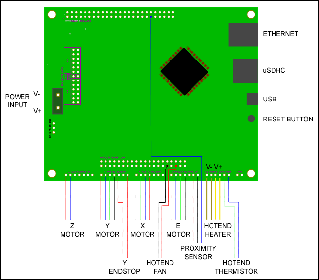
NOTE: that the order of the X motor wires are reversed compared to the Y, Z and Extruder motors. If you plug the X axis in the same as the other axes, the direction of movement of the X axis will be wrong.
| The wiring should now look like the image here. The proximity sensor wire is green in this picture, yours will be blue. Also, the picture shows the hot end fan wires connected to the top row of pins, while the wiring diagram shows it connected to the bottom row; either works. |  |