As with the Y axis, the Z axis is assembled in stages, starting with small sub-assemblies which are brought together towards the end.
Z axis sub-assemblies
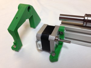
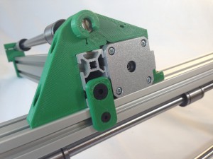
z-motor-mount
Begin with the z-motor-mount. You will need the following parts:
| Component |
Type |
Quantity |
| z-motor-brace |
Printed |
1 |
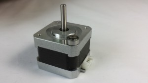
| NEMA17 stepper motor |
|
1 |
| M3x8mm countersunk socket screw |
Fastener |
1 |
| M3 washer |
Fastener |
1 |
| 623 bearing (10mm diameter) |
Hardware |
1 |
| M3x12mm countersunk socket screw |
Fastener |
3 |
| M4x12mm countersunk socket screw |
Fastener |
3 |
| M4 T-nut |
Fastener |
3 |
|
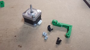 |
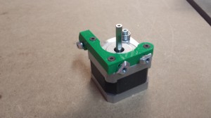
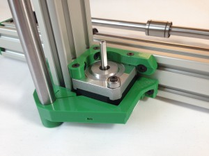
| Begin by securing the 623 bearing on the corner of the Z motor, with an M3x8mm countersunk socket screw. The M3 washer goes between the bearing and the motor body; check the bearing can rotate freely. |
 |
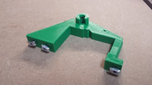
| Screw the z-motor-brace to the stepper motor using the M3x12mm countersunk screws, then loosely fit the M4 T-nuts with the M4x12mm countersunk screws, as shown. |
 |
z-lower-mount
The z-lower-mount sub-assembly requires the following:
| Component |
Type |
Quantity |
| z-lower-mount |
Printed |
1 |
| M4x12mm countersunk socket screw |
Fastener |
3 |
| M4 T-nut |
Fastener |
3 |
|
 |
| Loosely fit the M4 T-nuts as shown |
 |
z-upper-mount
The z-upper-mount sub-assembly requires the following:
| Component |
Type |
Quantity |
| z-upper-mount |
Printed |
1 |
| M3x35mm cap head screw |
Fastener |
1 |
| M3 nut |
Fastener |
1 |
|
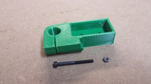 |
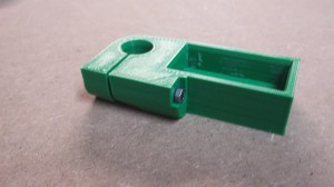
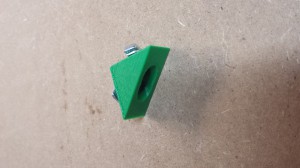
| Fit the M3 screw and nut as shown. |
 |
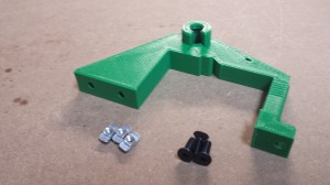
z-corner-bracket
The z-corner-bracket sub-assembly requires the following:
| Component |
Type |
Quantity |
| z-corner-bracket |
Printed |
1 |
| M4x12mm countersunk socket screw |
Fastener |
2 |
| M4 T-nut |
Fastener |
2 |
|
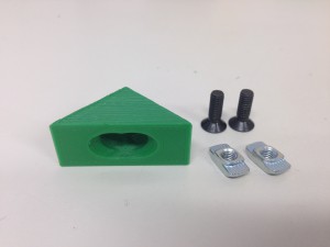 |
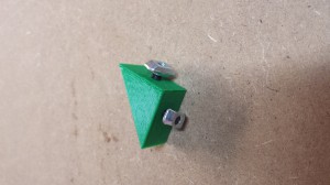
| Now loosely fit two M4 T-nuts using M4x12mm countersunk socket screws into the z-corner-bracket. |
 |
|
 |
Z axis assembly
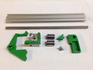
You can now bring all of the Z axis sub-assemblies together, using the following parts:
| Component |
Type |
Quantity |
| z-motor-mount |
Assembled |
1 |
| z-lower-mount |
Assembled |
1 |
| z-upper-mount |
Assembled |
1 |
| z-corner-bracket |
Assembled |
1 |
| LM12UU linear bearing |
Hardware |
2 |
| Smooth rod 12x350mm |
Hardware |
1 |
| Aluminium extrusion |
Hardware |
1 |
| M6x16mm countersunk socket screw |
Fastener |
2 |
|
 |
NOTE: THERE IS NO NEED TO SLIDE THE T-NUT IN FROM THE END OF THE ALUMINIUM EXTRUSION!
The M4 T-nuts are designed to drop into the extrusion slot. As the retaining screw is tightened, the T-nut rotates in the slot and locks into place.
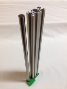
| Start by putting the z-upper-mount on the aluminium extrusion – it’s a tight fit. Try to put it on as squarely as possible, to avoid damaging the printed part. If you need to, use a wooden drift if you’re going to tap the aluminium extrusion with a hammer, to avoid damage to the aluminium! |
 |
| Check the aluminium extrusion is all the way in to the z-upper-mount. Secure the z-upper-mount with two M6x16mm countersunk screws. |
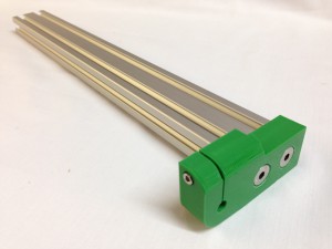 |
| Fit the 12x350mm smooth rod into the z-upper-mount. You may need to slacken off the clamp screw to get it in. Make sure it is pushed in as far as it will go; it should be level with the end of the aluminium extrusion. Tighten the clamp screw. |
 |
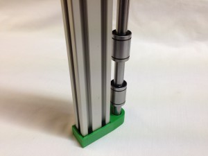
| Slide the LM12UU Linear bearings onto the smooth rod. Check they slide smoothly and freely. |
 |
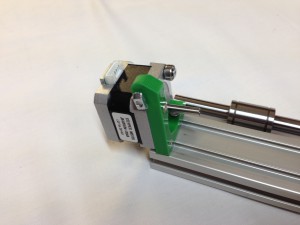
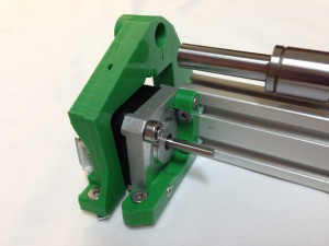
| Slide the z-motor-mount sub-assembly onto the end of the extrusion. Keep all of the M4 T-nuts loose to allow for moving the motor around. |
 |
| The z-lower-mount goes around the motor, and it’s easiest to put them on together. |
 |
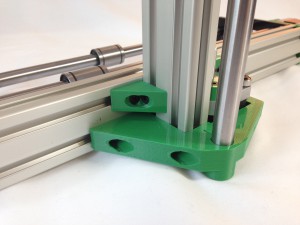
| Hook the z-lower-mount over the motor, and move them together up the aluminium extrusion. The smooth rod should engage in the hole of the z-lower-mount; make sure it is pushed on as far as possible. |
 |
| Lightly tighten the two M4 T-nuts on the z-motor-mount that are engaged in the aluminium profile slot. The M4 T-nuts should not be done too tight at this stage; just enough to hold the Z motor to the extrusion. |
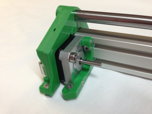 |
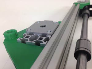
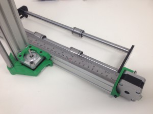
| The assembly from another angle. Try to orientate the T-nuts horizontally, so they can drop into the Y axis aluminium extrusion easily. |
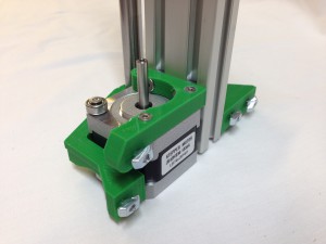 |
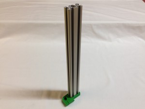
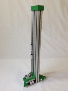
| The complete Z axis assembly. |
 |
Connecting the Z axis assembly to the Y axis assembly
| The Z axis assembly can now be attached to the Y axis assembly. Orientate the Z nuts so they drop into the extrusion, you don’t need to slide it on from the end. |
 |
| As you tighten the M4 countersunk screws, the T-nut should rotate 90 degrees and catch in the extrusion slot. They may need a wiggle to get them to turn. Assemble loosely to start with, so you can move the components to the correct places. |
 |
| The base of the vertical Aluminium extrusion must be flush with the bottom of the Y axis extrusion. The bottom of the motor will be a little below the level of the extrusions. |
 |
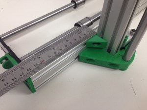
| On the Y axis motor side, the face of the Z axis aluminium extrusion should be 210mm from the end of the Y axis aluminium extrusion. The picture shows 205mm, which only just gives enough clearance; 210mm is safer. |
 |
| On the Y axis idler side, the face of the Z axis aluminium extrusion should be 120mm from the end of the Y axis aluminium extrusion. The picture shows 125mm; 120mm has proved to be better. |
 |
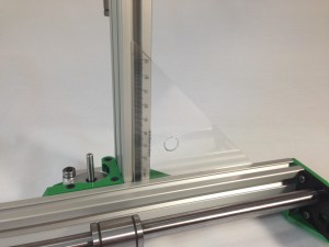
| Use the supplied set square to check the Z axis and Y axis extrusions are at right angles to each other, before finally tightening of the screws. Repeat the above alignment steps to confirm they are all correct, before tightening all the fasteners. |
 |
| Component |
Type |
Quantity |
| ZY assembly |
Assembled |
1 |
| z-foot |
Printed |
1 |
| M6x16mm countersunk socket screw |
Fastener |
1 |
| M4x8mm countersunk socket screw |
Fastener |
1 |
| M4 T-nut |
Fastener |
1 |
|
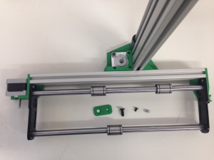 |
| The base of the vertical Aluminium extrusion must be flush with the bottom of the Y axis extrusion. These two can then be secured using the z-foot, one M6x16mm countersunk socket screw, and an M4 T-nut and M4x8mm countersunk socket screw. |
 |


