Connecting the ATX Power PCB and the Duet PCB
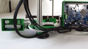
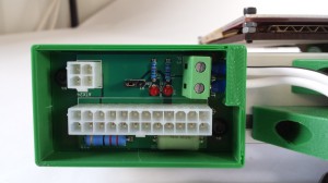
| Power to the machine is provided by a standard ATX PC power supply. The 24-pin ATX connector and the 4-pin Aux power connector plug into the ATX-Power circuit board. This breaks out the 12v line to the 2-way screw terminal for powering the machine through the main Duet board. |
|
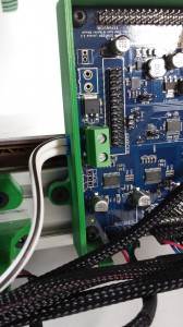
| The two circuit boards are connected by a length of two-core cable, as shown. Polarity is important. It is advisable to use the strand marked with the black line as the negative side. The top screw terminal connection on both boards is the negative terminal (with them fitted as shown). NOTE: As of firmware 0.78, the proximity wire is shown in the incorrect position in this picture. Refer to the ‘Wiring’ instructions. |
 |
| Four crimps are supplied with the wires, which need to be crimped onto the bare ends of the wires. You need a good, square, crimping tool, or the crimps won’t fit well in the terminals. If you don’t have the crimp tool, ‘tin’ the ends of the wires with a soldering iron and solder, for a good connection. Do not put bare wires into the terminals – they can work loose, and generate heat – enough to melt the terminals and destroy the board. The wires carry a lot of current, so make sure the terminals are tight, for a good connection. Pull on the wires to check they are not loose. Check every so often that the screw terminals are still tight. |
 |
| The ATX-Power circuit board has a 3-way male pin header, which should be fitted with a jumper across the two pins closest to the ATX 4-way connector. There are also two LEDs to indicate correct operation. |
 |
DO NOT CONNECT THE ATX POWER SUPPLY YET!
In the next instructions, you will power the Duet board via USB first, and confirm everything is working correctly, before applying 12V power.
