Heated bed wiring harness
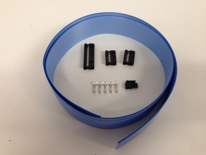
The bed wiring harness provides power to the heated bed and carries the signal from the thermistor to the Duet board. You will need these parts:
| Component |
Type |
Quantity |
| Ribbon cable 26-way |
Electronics |
850mm |
| IDC 2×13 connector |
Electronics |
1 |
| IDC 2×6 connector |
Electronics |
2 |
| Female crimps – 3030T-1 |
Electronics |
2 |
| Male 2-way terminal – 3025-02 |
Electronics |
1 |
|
 |
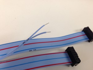
Preparing the heated bed end
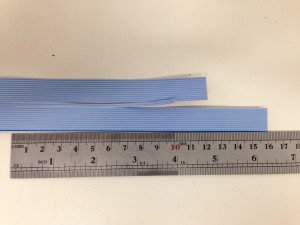
| Start by splitting the 26-way ribbon cable down it’s length. We need three separate groups of wires; two groups of 12 wires on the outside, leaving one pair of wires in the middle. |
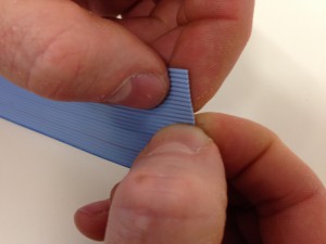 |
| You can simply tear the wires of the ribbon cable apart. |
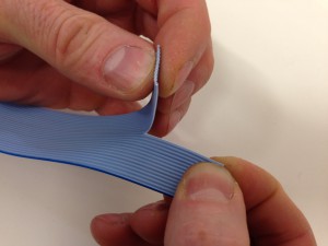 |
| The outside two parts should be 12 wires each, leaving 2 wires in the centre. Split this back 160mm from the end. |
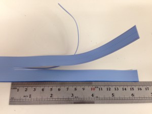 |
| Cut ONE of the 12-wire sections back 40mm. Cut the central 2 wires back 60mm from the end (sharp scissors are easiest for a straight cut). |
 |
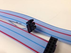
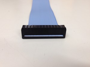
Fitting the heated bed-end IDC connectors
| Connect the two IDC 2×6 connectors on the end of the two 12-way ends. Try to match the orientation shown in the pictures, it will help fitting. However, it’s not too much of a problem; you can simply fold the ribbon cable back on itself, around the IDC plug, to get it on the right side. This makes the cable a little shorter, but not much. The IDC plugs fit on the connectors either way around. |
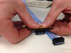 |
| You can do this by hand; make sure the connector is square to the cable, and use a piece of wood to press on – it’s easier! |
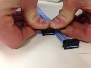 |
| Make sure the connector is fully pushed down. |
 |
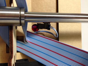
Fitting the thermistor connector
| Strip 4mm of insulation from central 2 wires. |
 |
| Crimp a female connector onto each one. |
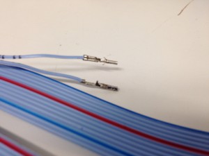 |
| Insert the crimps into the crimp housing. Polarity isn’t important for the thermistor. |
 |
Fitting the Duet-end IDC connector
| Cut the ribbon cable to 820mm, and connect the IDC 2×13 connector to the other end of the ribbon cable. It should face the other way from the IDC 2×6 connectors. |
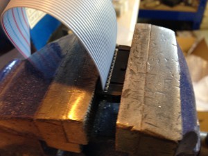 |
| It’s easiest to do this in a vice. |
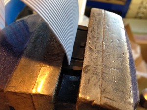 |
| Again, check that the cable is fully pushed into the connector. |
 |
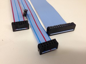
The finished heated bed wiring harness
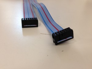
| The finished heated bed wiring. |
 |
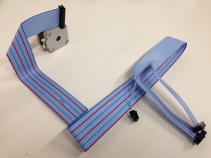
| This is the rough layout of the wiring on the printer. The 2×13 IDC connector plugs into the Duet board, the 2×6 IDC connector plugs into the heated bed, and the central connector plugs into the thermistor in the centre of the heated bed. |
 |
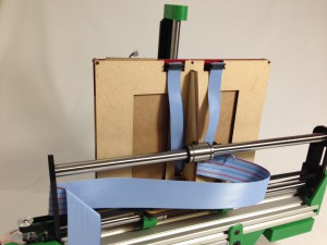
Fitting the bed wiring harness
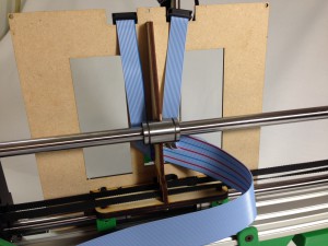
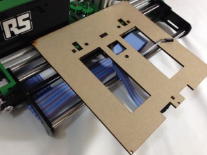
| Start by turning over your printer. From underneath, thread the longest 12-way section of the bed wiring harness up through the central slot in the bed, then back down, as shown. |
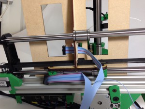 |
| Make sure it reaches the cut out in the MDF bed, that it is designed for. Put a 45 degree bend in the cable. Thread the other shorter side up to the second slot. |
 |
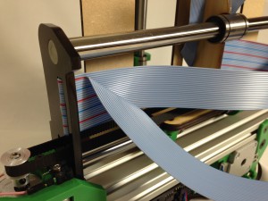
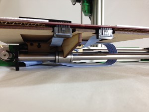
| Leave a good length of the main wire under the printer, and clip a loop of the ribbon cable into the slot near the Y axis motor. |
 |
| Run the cable up the back of the machine, and bend it over to connect to the bed power pins on the Duet board, as shown. |
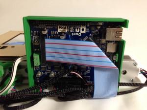 |
CAUTION!
Pay particular attention when connecting the heated bed ribbon cable to the Duet board, as above. If you put it in the wrong place, or miss-register the ribbon cable on the pins, 12V can run down the 3.3V line of the thermistor (the central two pins), and will immediately destroy the main processor when you turn the heated bed on. We regard this mistake as a user error, and is NOT covered by the warranty. |
| Adjust the ribbon cable as necessary to make it neat. |
 |
Fit the heated bed
| Put the heated bed, which you constructed in an earlier step, on the top of the Y carriage. The four corner screws should fit into the MDF bed. |
 |
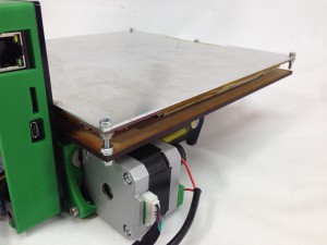
| If you followed the section in the ‘Heated bed assembly’ instructions to assemble the heated bed for ‘Swiss’ clips, and/or for a manually adjustable bed, the bed is supported on the three longer screws. The bed rests on the M3 nyloc nuts, which provide adjustment. You can add an M3 nut underneath, to lock the bed in position. |
 |
| A view of the adjustable bed from the back. |
 |
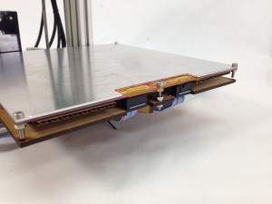
| Make sure the thermistor wire is accessible underneath. Yours may be on the other side of the y-axis-rib, but it doesn’t matter. Plug the thermistor into the connector, which is attached to the central two wires of the ribbon cable. Tuck it into a position so it doesn’t rub on the linear rod. |
 |
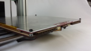
| Plug the two IDC connectors into the bottom of the heated bed PCB. |
 |
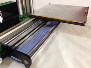
| Finally, check that the movement of the Y axis allows the ribbon cable to fold neatly under the bed. Adjust as necessary. |
 |
| Test with the Y carriage at the extremes of the axis. |
 |
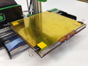
Fit the print surface
| The print surface clips onto the heated bed using the four foldback clips. The glass plate is rectangular, not square. Its long side should run along the Y axis, as on the completed printer shown here, otherwise the clips won’t hold the glass. |
 |
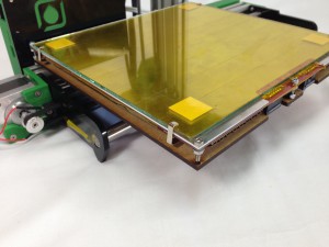
| If you have the alternative ‘Swiss’ clips, they clip over the glass, aluminium and PCB, as shown. For them to fit, the heated bed needs extra space between the heated bed and MDF sheet; follow the ‘Alternative build’ instructions on the ‘Heated bed assembly’ page. |
 |
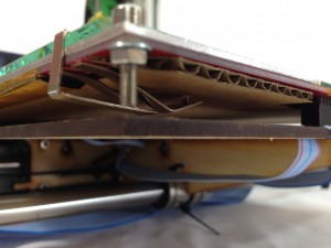
| The clip seen from under the bed. It can hook into the cardboard. If you have foldback clips and want to get the ‘Swiss’ clips, they are available from our webshop. |
 |
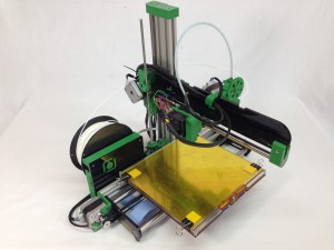
| This is how the bed will look on the completed machine. Please note, the picture shows the extruder, hot end and wiring, which you have not done yet! |
 |


