Contents
Y carriage assembly
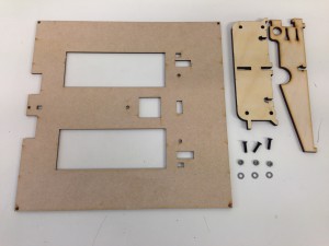
The Y carriage can now be assembled and fitted. You will need the following parts:
| The y-axis-rib slots into the y-axis-cross rib. Make sure the tab on the y-axis-cross rib is on the left side, as shown in the picture. This activates the Y axis endstop, so needs to be on the correct side. | 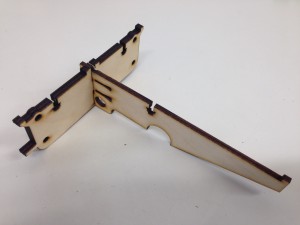 |
| Secure the bed-insulator to the Y axis ribs using the three M3x12mm countersunk socket screws. The washer and nut go in the captive part of the wood. | 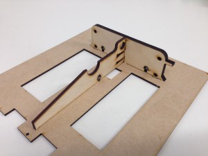 |
| Make sure the bed-insulator is orientated correctly, as shown in the picture. The slots on the outside edge are not symmetrical; the heated bed PCB only fits one way around. | 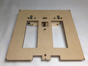 |
Y-carriage mounting
Fit the y-carriage to the assembled y-z-axis assembly. The following parts are required:
|
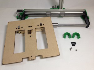 |
| Slide the y-bearing-clamps onto the bearings as shown. Note the position of the mount on the bearing. This is important to allow maximum movement of the Y axis in its frame. | 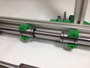 |
| Offer up the y-carriage assembly to the y-bearing-clamps. Drop an M3 nut into the captive hole in the y-bearing-clamp on each side, and screw in the M3x16mm cap head screws, loosely for now. | 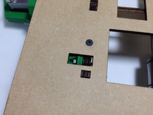 |
| Turn the machine over, drop an M3 nut into the captive hole in the y-bearing-clamp on each side, and screw in the M3x16mm cap head screws. Now tighten all the bearing mount screws. As you tighten them, keep moving the axis back and forth along the axis between turns of each screw. This will let the bearings settle in the right place, and ensure the axis runs smoothly. | 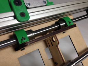 |
| Clip the y-axis-rib over the front linear bearing to complete the y-carriage. | 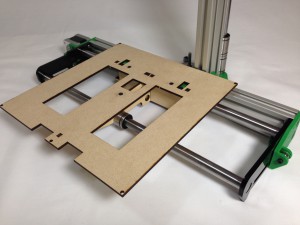 |
Y axis drive belt
|
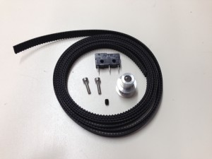 |
| Cut the 1/4″ MXL belt to 710mm. This is for the X axis, so set it aside, and leaves approximately 990mm for the Y axis. | |
| Mount the microswitch with the two M2.5x10mm cap head screws. These should self-tap into the plastic of the y-motor-mount. Do not widen these holes with a drill, or the screws won’t hold. The switch should align with the hole in the laser cut y-axis-end-plate. Check the Y-carriage tab can hit the switch. | 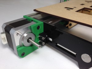 |
| There are two slots and a circular hole in the y-rib. From the Y axis motor end, slide the end of belt through the wide part of lower slot, teeth downwards, and back through the upper slot, as shown. Push the belt back into the narrowing slot to lock it in place. | 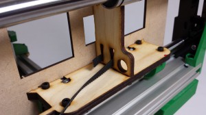 |
| Put the pulley on the motor shaft, as shown in the picture. The motor shaft has a flat on it; align the grub screw with this, and tighten the grub screw using a 1.5mm Allen key. Thread the belt through the top hole in the y-axis-end-plate, around the drive pulley, and back through the lower slot in the y-axis-end-plate. | 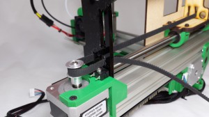 |
| Twist the belt 180 degrees before feeding it through the circular hole in the y-rib, then through the lower slot in the idler end y-axis-end-plate. | 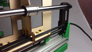 |
| Pass the belt over the idler bearing, back through the top slot in the y-axis-end-plate, towards the y-rib. The belt should run on the idler bearing on the smooth side of the belt, not the teeth. | 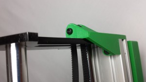 |
| Pull the belt tight and lock it by engaging the teeth of the two ends of the belt, then push them both to the back of the lower slot as shown. Trim excess belt, leaving a short length for adjustment. You can adjust belt tension by overlapping the belt ends more, so an extra tooth is engaged. | 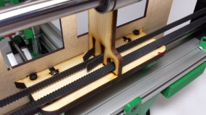 |
Y belt tensioning and carriage slipping
| The belt tension needs to be quite tight, or the axis will suffer from ‘backlash’, and you will not get smooth vertical walls in your prints. When you twang the bottom belt, which has the longest uninterrupted span, a just-audible note should be heard. For reference, the note of the lowest string of a bass guitar is suitable. This is the bottom ‘E’ string; search online for a bass guitar tuner if you need an example. Adjust the belt as required. |  |
| The belt needs to be tightly held in the slot. If it is able to move, you will get steps in your prints. To test if it is, hold the y-pulley at the motor, and push the y-carriage each direction, while looking at the belt. if the doubled-belt is able to move in the slot, you may get steps in your prints. The belt end that goes through the top slot rarely slips, so you will tend to find it slips in one direction. | |
| To improve the belt grip, put a cable tie around the two belts, push it hard up against the y-axis-rib, then tighten. The cable tie in the picture has been wrapped around the belt twice, but you can alternatively use a couple of cable ties. | 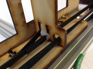 |
| RepRap Ormerod forum (here) members have come up with a number of different designs, offering more clamping and belt tension adjustment, should you need it. | |

