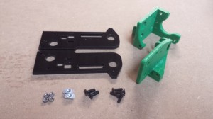
Y axis sub-assemblies
Y-motor-end and Y-idler-end
TIP: Click on the bold names of the printed parts in the component lists. This opens a new window, showing the part in the Github stl viewer, so you can identify the part more easily.
| Component |
Type |
Quantity |
| y-idler-bracket |
Printed |
1 |
| y-motor-bracket |
Printed |
1 |
| y-axis-end-plate |
Lasercut |
2 |
| M3 Nut |
Fastener |
4 |
| M4 T-nut |
Fastener |
2 |
| M4x12mm countersunk socket head screw |
Fastener |
2 |
| M3x12mm countersunk socket head screw |
Fastener |
4 |
|
 |
TIP: Click on pictures in the instructions to see a larger version.
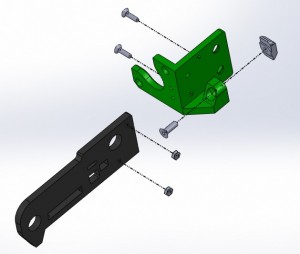
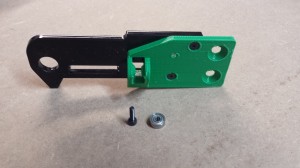
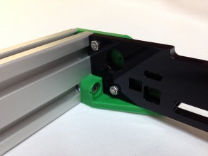
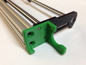
| Begin by assembling the Y-motor-end, as shown. Use y-axis-end-plate ‘A’ with the y-motor-bracket. The 12mm holes will be slightly larger in diameter on one side of the y-axis-end-plate, the side with the letter ‘A’, which will make it easier to insert the 12mm ground steel bar later. |
 |
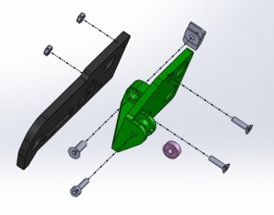
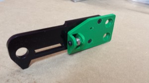
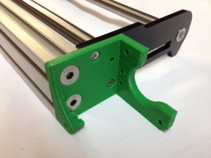
| Repeat with the y-axis-idler-bracket, using y-axis-end-plate ‘B’, to build the y-idler-end. |
 |
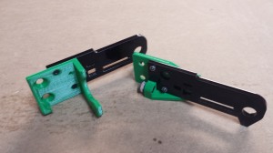
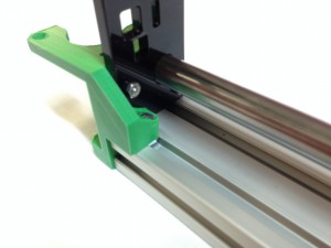
| The Y axis ends assembled. |
 |
Y-idler-end bearing
Now fit the 623 idler bearing to the y-idler-end, for which the following are required:
| Component |
Type |
Quantity |
| y-idler-end |
Assembled |
1 |
| M3x12mm cap head screw |
Fastener |
1 |
| 623 bearing (10mm diameter) |
Hardware |
1 |
|
 |
| The retaining screw (M3x12mm) should self tap into the printed part, with no need for a nut on the free end. It may require a fair bit of force to push the bearing into position. |
 |
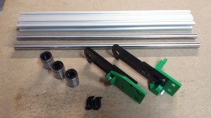
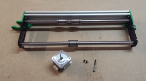
Y axis frame
The next step is to assemble the Y axis frame. For this you will need the following:
| Component |
Type |
Quantity |
| y-idler-end |
Assembled |
1 |
| y-motor-end |
Assembled |
1 |
| Aluminium extrusion |
Hardware |
1 |
| LM12UU Linear bearing |
Hardware |
3 |
| Smooth rod 12x350mm |
Hardware |
2 |
| M6x16mm countersunk socket head screw |
Fastener |
4 |
|
 |
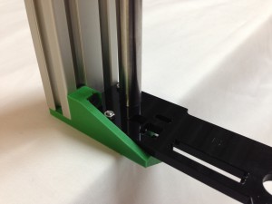
| Screw the y-idler-end onto the Aluminium extrusion, using two M6x16mm countersunk socket screws. These screws need to be tight – if they are loose, the X axis will not be level to the bed. |
 |
| Ensure the M4 T-nut is located in the extrusion slot, and tighten. |
 |
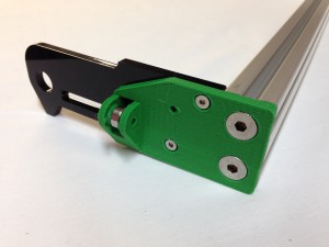
| With the y-idler-end supported by the edge of a table, take one of the 12x350mm smooth rods and push it into the hole in the acrylic end piece that is closest to the aluminium extrusion. The 12mm diameter holes are sized to be an interference fit with the rods, and the Acrylic laser cut plates are quite brittle so care must be taken when inserting the rods not to break the end plates. |
 |
| NOTE: Some 12x350mm smooth rods are actually a little longer; they may be as much as 352.5mm long, due to variability in manufacture. The printed part of the y-idler-end has been updated to accommodate this, with a pocket. The other places that the rods are used can similarly accommodate these rods (Z axis), or it doesn’t matter (X axis, Y axis front rod) – the rod will poke out the end a couple of millimetres. If you have longer rods, and NO pocket in the y-idler-end, contact support for updated parts. |
| With the acrylic supported, push the second 12x350mm smooth rod into the hole in the end of the plate. Keep the rod perpendicular to the plate whilst pushing. You can use a small hammer on a piece of wood on the end of the rods if necessary. |
 |
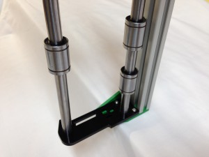
| Slide the LM12UU Linear bearings onto the smooth rod, two onto the rod closest to the aluminium extrusion, and one on the front rod. Check they slide smoothly and freely. |
 |
| Push the y-motor-end onto the smooth rods at the other end. Try and keep the smooth rods as straight as possible, to avoid damaging the acrylic parts. Push them home, so that the motor mount is flush with the aluminium extrusion. |
 |
| Screw the y-motor-end onto the Aluminium extrusion, using two M6x16mm countersunk socket screws. These screws need to be tight – if they are loose, the X axis will not be level to the bed. |
 |
| Ensure the M4 T-nut is located in the extrusion slot, and tighten. |
 |
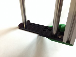
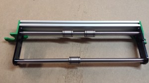
| The completed assembly. Check all screws are tight. |
 |
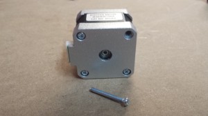
Y axis motor
Now you can fit the Y axis motor. For this step you will need the following:
| Component |
Type |
Quantity |
| y-axis-frame |
Assembled |
1 |
| NEMA17 stepper motor |
|
1 |
| M3x8mm countersunk socket screw |
Fasteners |
2 |
| M3x40mm socket cap screw |
Fasteners |
1 |
|
 |
| One screw needs to be removed from the back of the motor as shown. |
 |
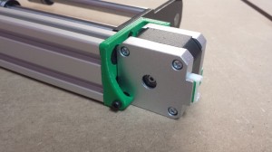
| Fit the motor into the printed y-motor-bracket. Secure the motor in place with 2 x M3x8mm countersunk socket screws in the front face |
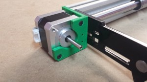 |
| Put one M3x40mm socket cap screw in the back, where you took out the motor screw. |
 |


