
Build Instructions – Base Assembly – Tower Assembly – Panels and Rods – Effector Assembly – Extruder Drive
Hot End Assembly – Electronics – Bed, Top Plate and Belts – Commissioning – Printing – Troubleshooting
Goal
By the end of this section, you will have built the hot end, assembled it with the effector, 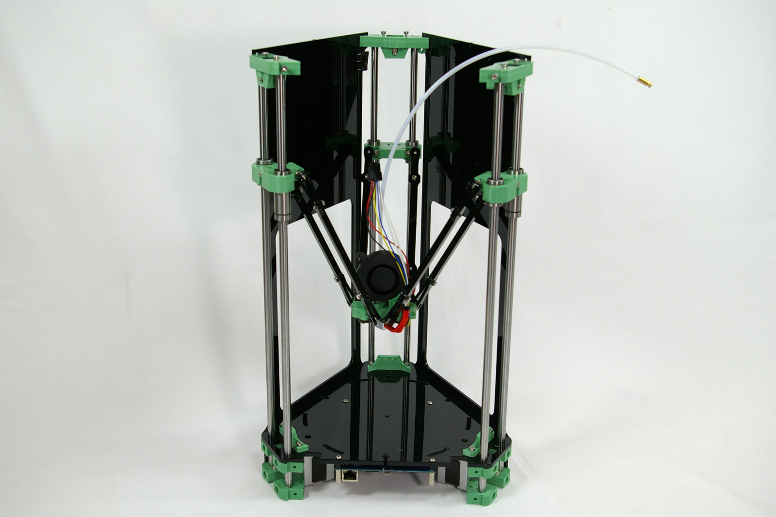
and installed it in the printer frame.
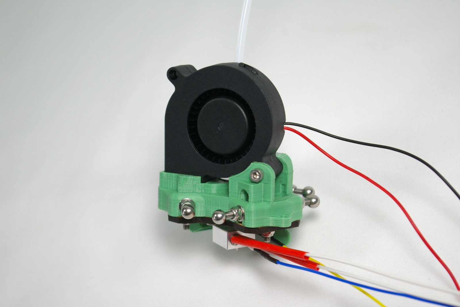
The hot end melts the filament, and extrudes it, to build the 3D printed object.
(The image shows a terminator on the free end of the PTFE tube. This is no longer needed.)
Crimps
These are the small metal pins and sockets attached to the ends of wires by pinching parts of themselves (“crimping”) to grip the wire. The ends of the fan, thermistor and heater wires are fitted with crimps pinched onto the ends of their wires. There are many types and shapes. The ones fitted onto the hot end components are designed to fit into a connector block. The barbs on them latch onto plastic tags inside the slots of the connector block, holding them in place. It is therefore important to insert them the right way round so they fit correctly and click into place, and to be aware that once they’re in, they’re very difficult to get out again.
Assemble the Hot End Components
Nozzle Assembly
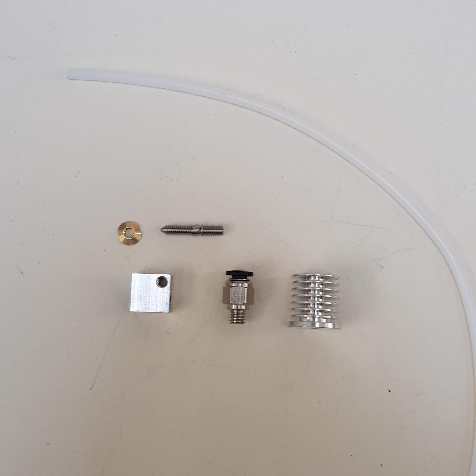
The nozzle is where the filament is heated and extruded from. You will need the following parts:
| # | Component | Qty | Type | |
| 1180 | Tapered nut | 1 | Hot end |
|
| 739 | Heater block | 1 | Hot end | |
| 1179 | Threaded nozzle | 1 | Hot end | |
| 1136.1 | Heatsink | 1 | Hot end | |
| 1055 | Bowden Tube | 1 | Hot end |
| Screw the nozzle into the base of the heatsink by hand. | 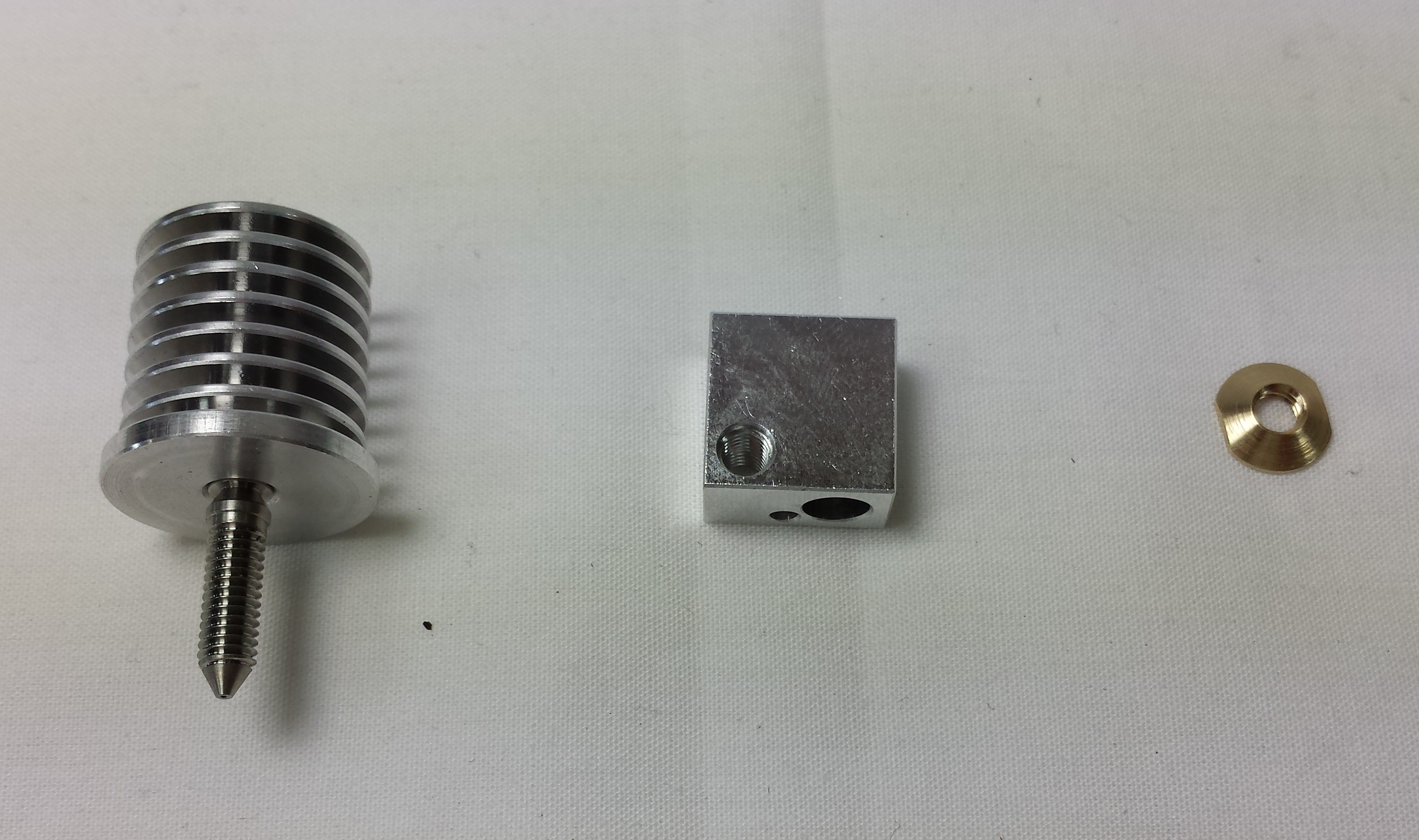 |
| Screw the heater block onto the nozzle, again by hand. There is not need to use any tools at this stage. Take care to fit the heater block with the small hole nearest the nozzle tip. | 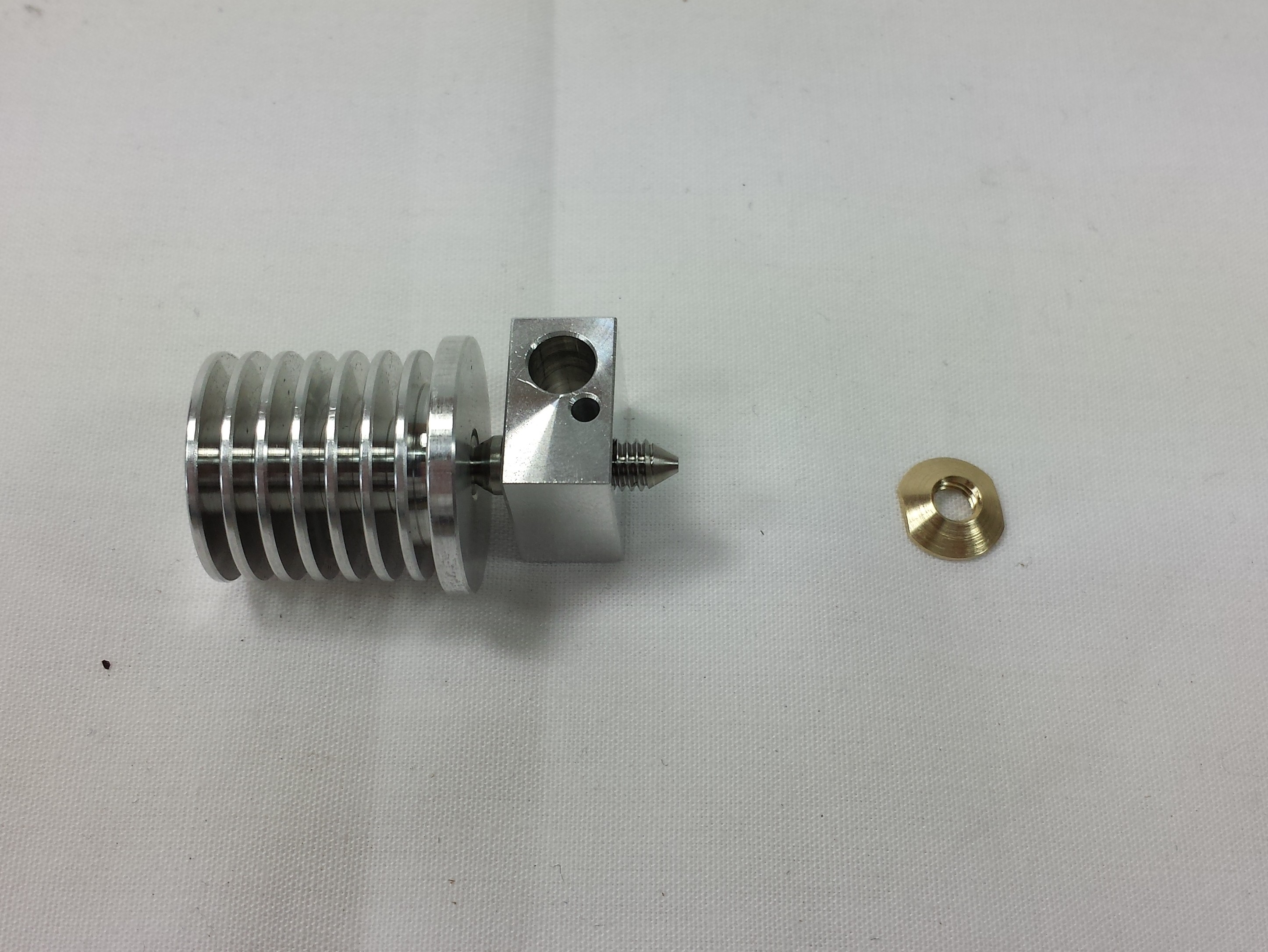 |
| Fit the brass nut. Using an 8mm spanner, gently tighten the assembly until it is just over ‘finger tight’. Hold the heater block and tighten the nut, leaving the heatsink and nozzle free to rotate. The constriction in the nozzle has a very thin wall (to reduce heat conduction), so care should be taken not to over tighten the assembly as it may result in snapping the nozzle. | 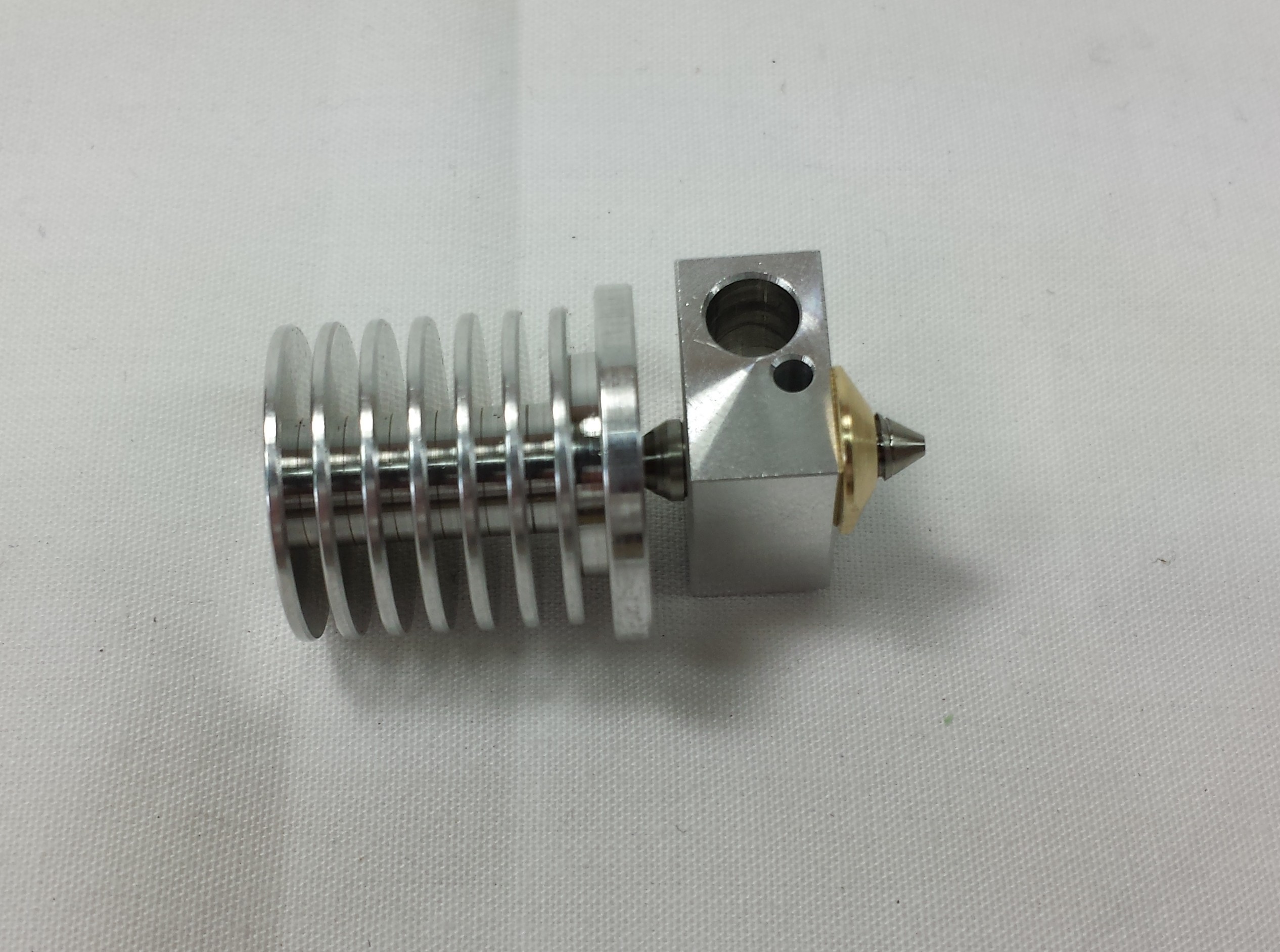 |
| Screw in the pneumatic fitting to the heatsink. There is no need to use a spanner, hand tightening is sufficient. | 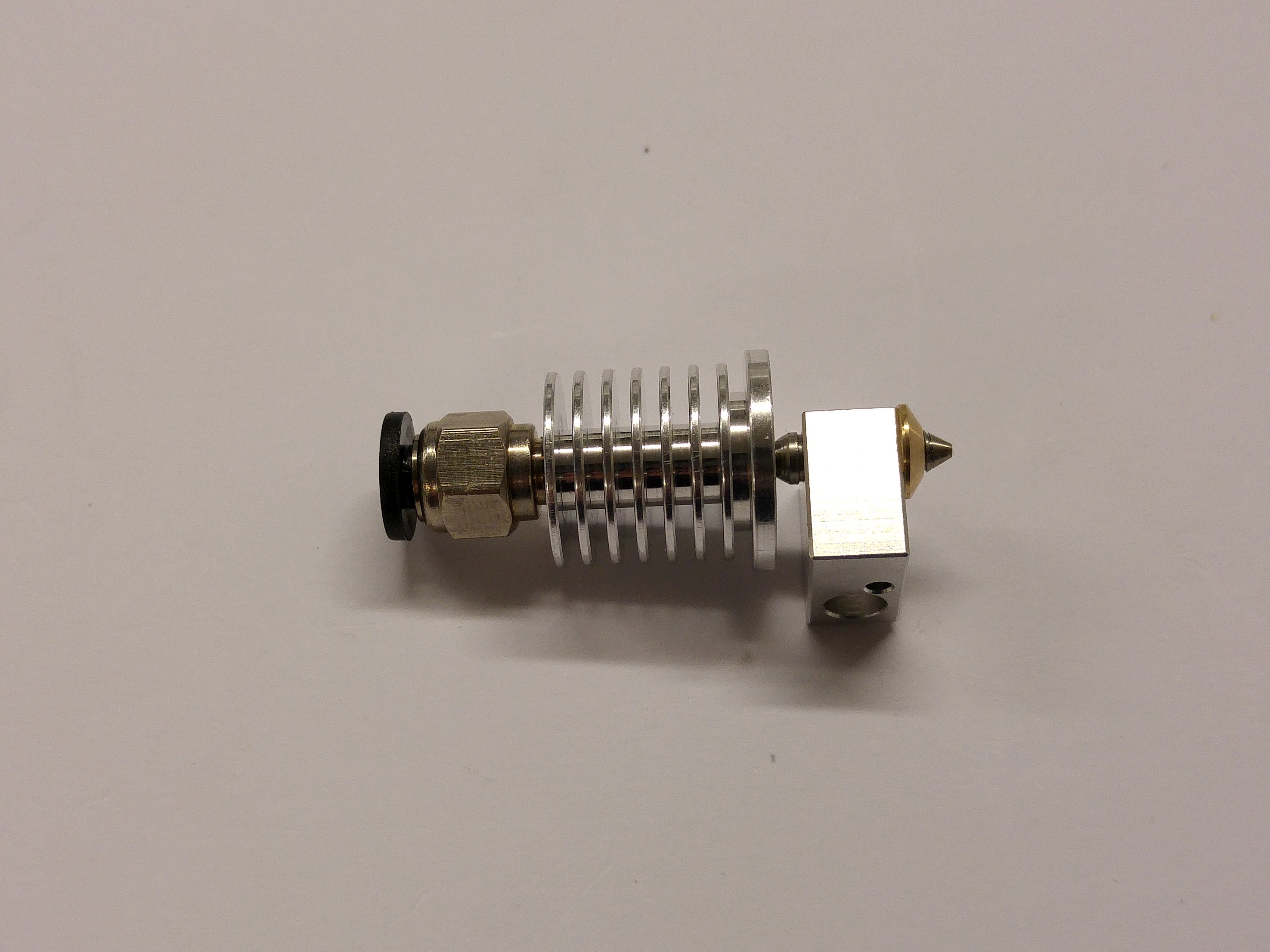 |
| Check the ends of the PTFE Bowden tube are clean and cut square. If needed, use a scalpel or craft knife to make a clean cut. | 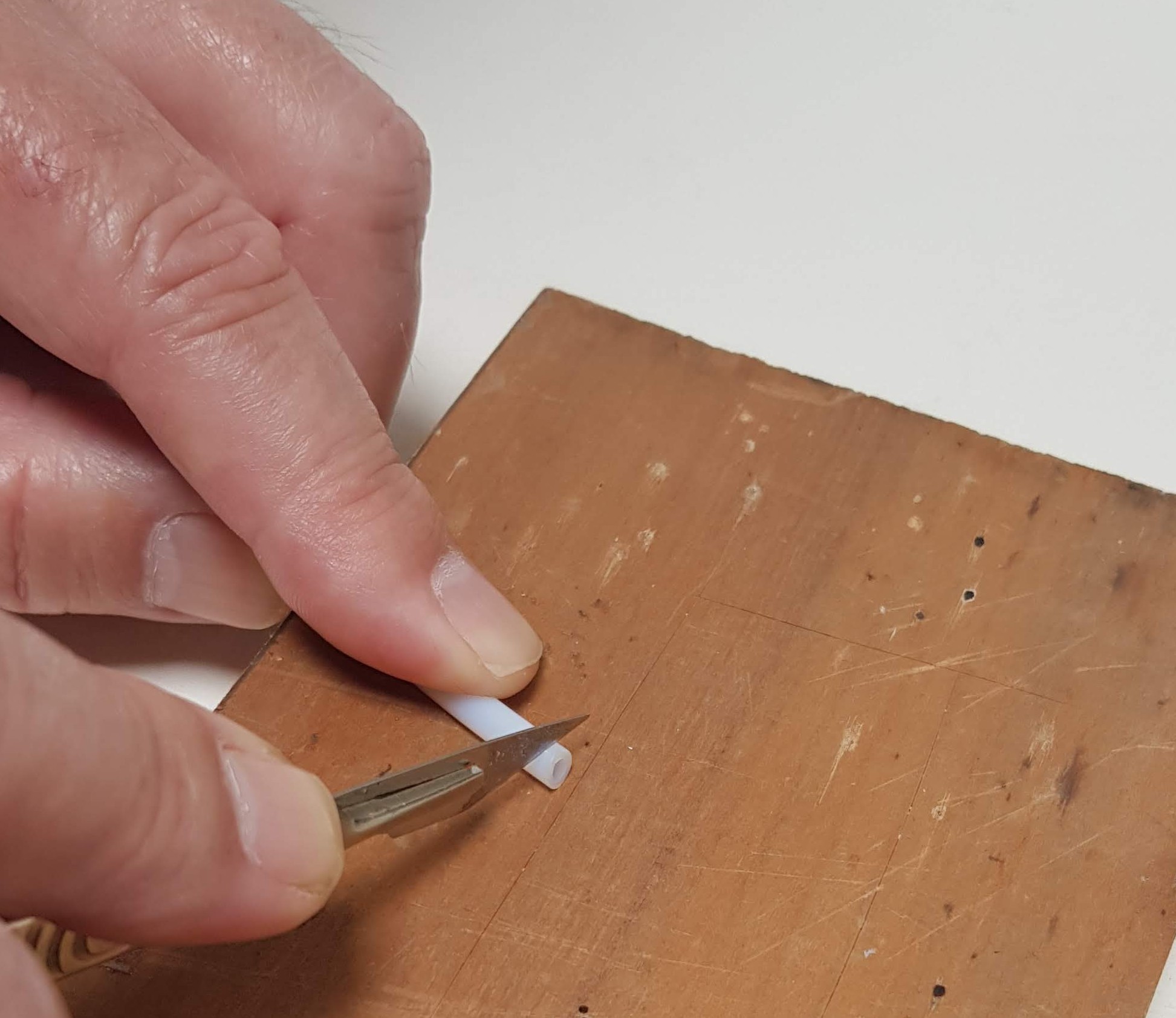 |
| Insert the Bowden tube into the pneumatic fitting. | 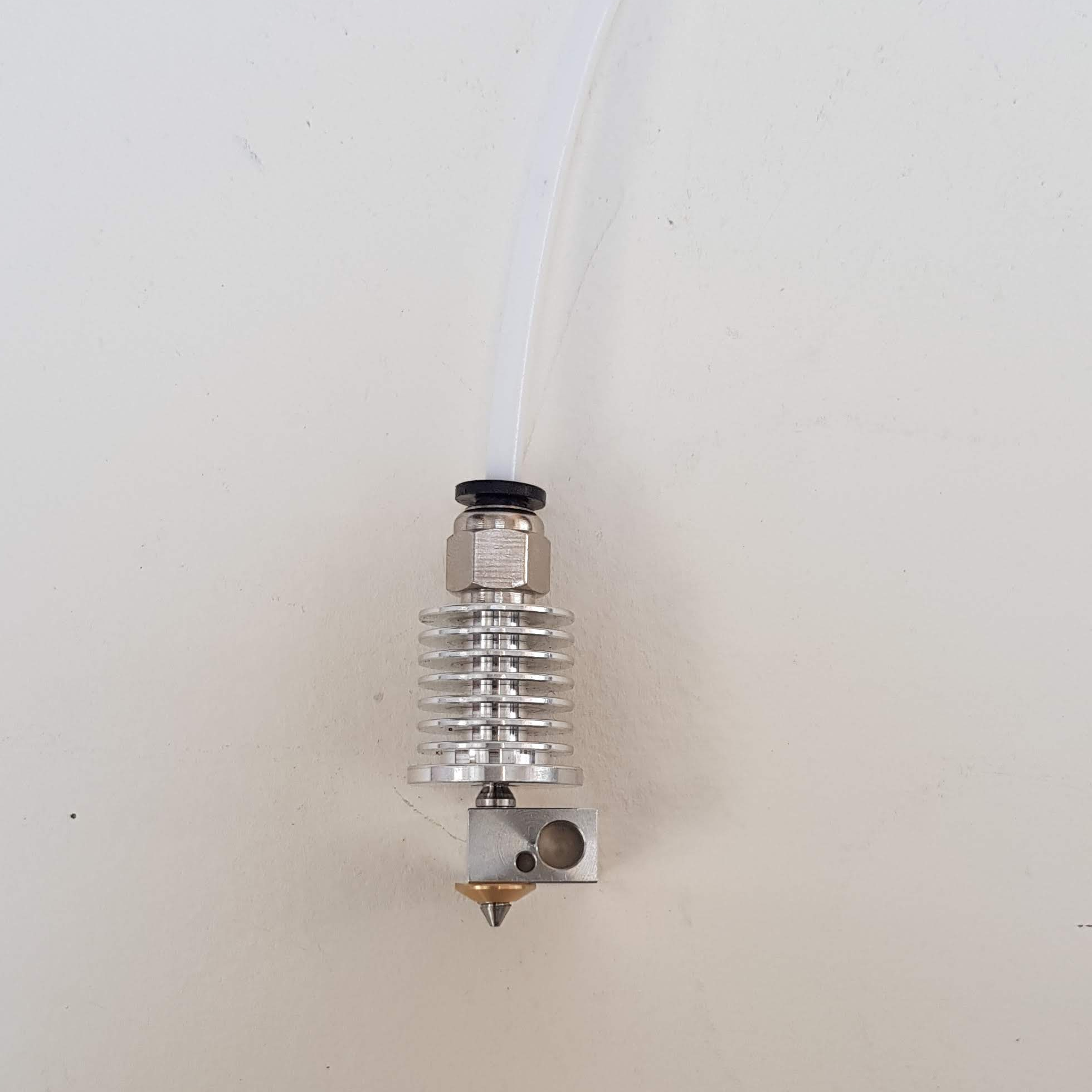 |
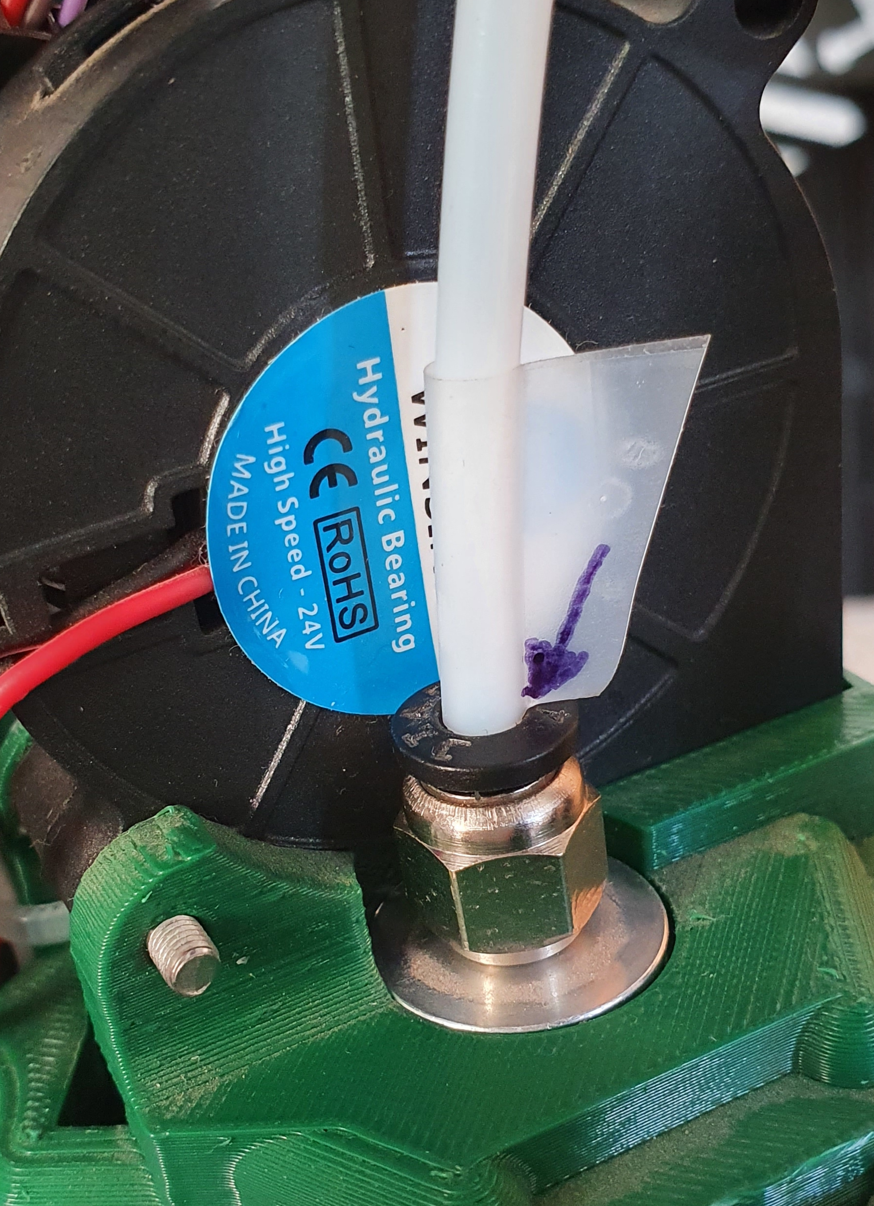
| The pneumatic fittings grip the PTFE tube tightly. But if, by mistake, you try to drive filament into the hot end when it is too cold the tube can sometimes slip out a little way. This is hard to see. So put a short piece of sticky tape round the PTFE tube as shown so it just touches the top of the pneumatic fitting. Then in the future you will be able to see if a gap opens up.
Add another piece of tape to the PTFE tube where it goes into the pneumatic fitting on the extruder drive. If a gap opens up later, push the tube back in with the hot end at full temperature. Be careful not to touch the hot part of the hot end. Then extrude, say, 100mm of filament to clear the hot end through. |
 |
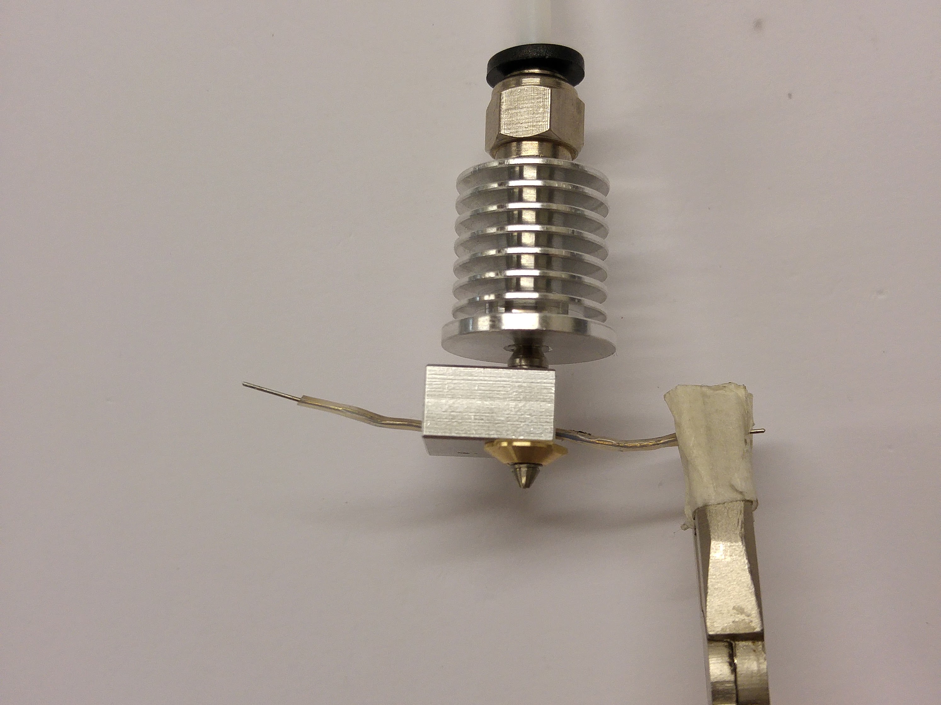
Test the Cartridge Heater
The cartridge heater provides the heat for the hot end.
You will need the following parts:
| # | Component | Qty | Type | |
| 662 | Cartridge heater 19v | 1 | Hot end | 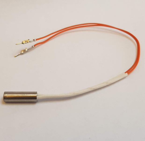 |
| Check the resistance of the heater cartridge. It should be around 10 to 11 ohms. | 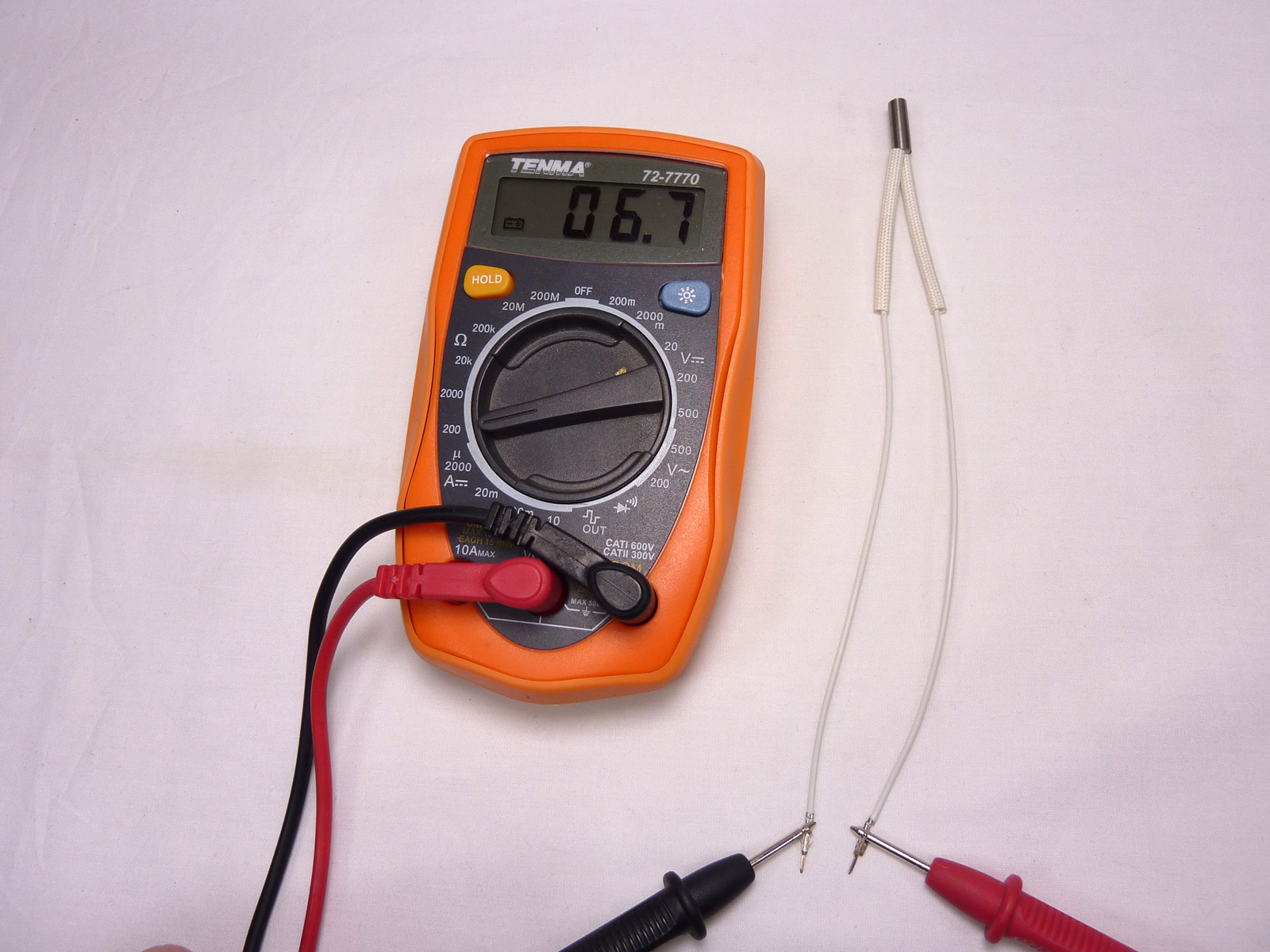 |
Thermistor
The thermistor is the temperature sensor for the hot end, and makes sure the hot end stays at the correct temperature. You will need the following parts:
| # | Component | Qty | Type | |
| 430 & 167 | Thermistor with PTFE heatshring surround | 1 | Hot end | 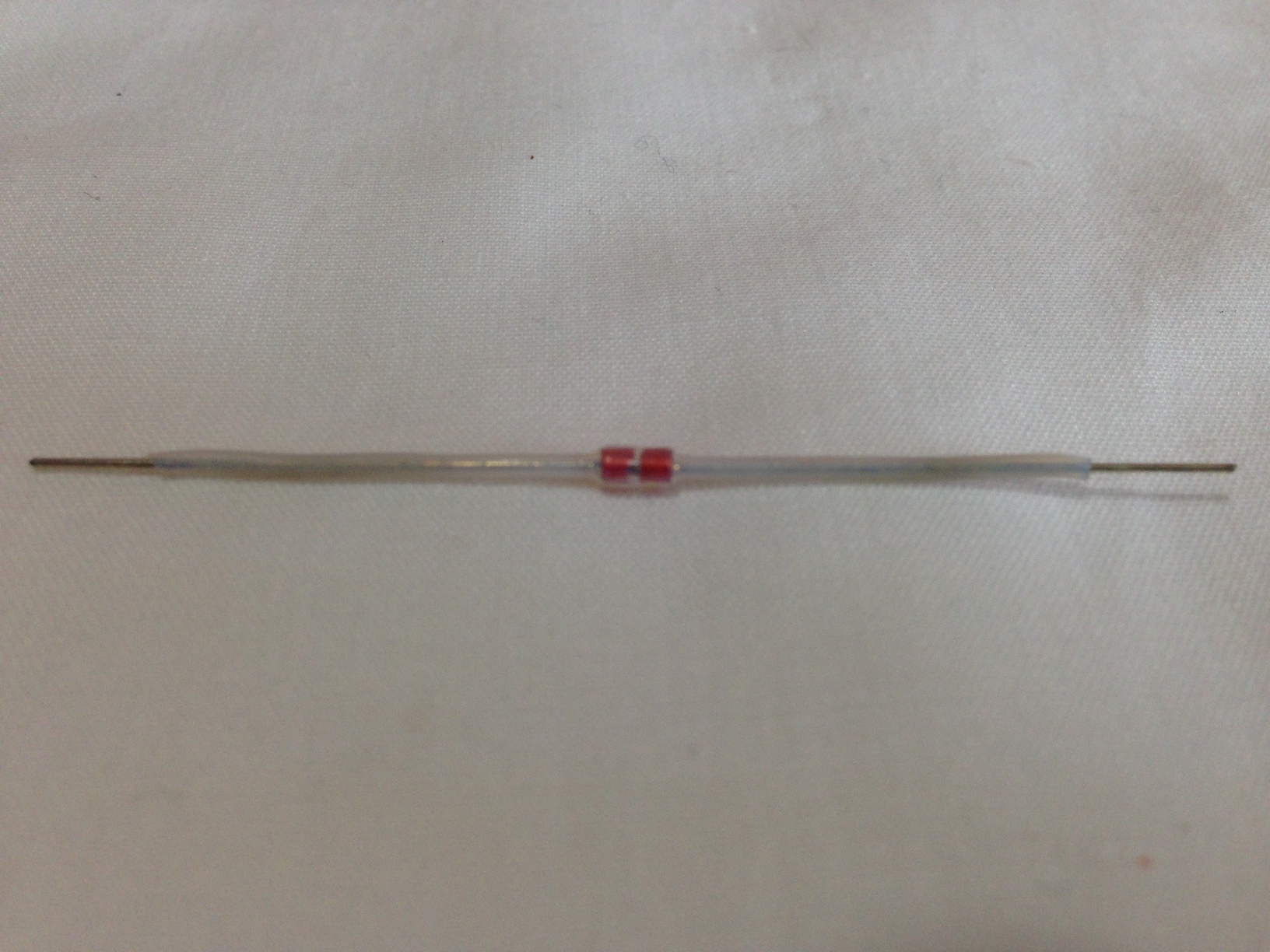 |
The thermistor supplied with our kits comes with the PTFE heatshrink pre-shrunk on to it.
Thermistor Wires
These wires connect the thermistor to the wiring loom.
| # | Component | Qty | Type | |
| 433 | Thermistor wiring – 160mm | 2 | Hot end | 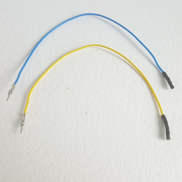 |
| Thermistor wires should each have the female crimp wrapped in heatshrink. | 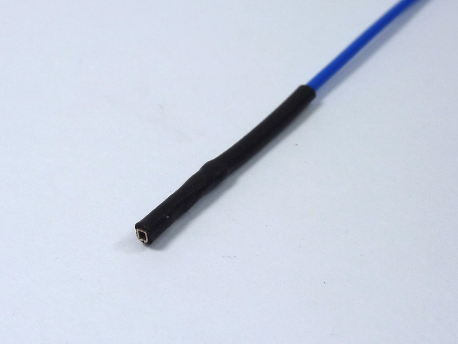 |
Assemble the Hot End and Effector
The hot end is mounted in the effector. You will need the following parts:
| # | Component | Qty | Type | |
| Hot end assembly | 1 | Assembled | 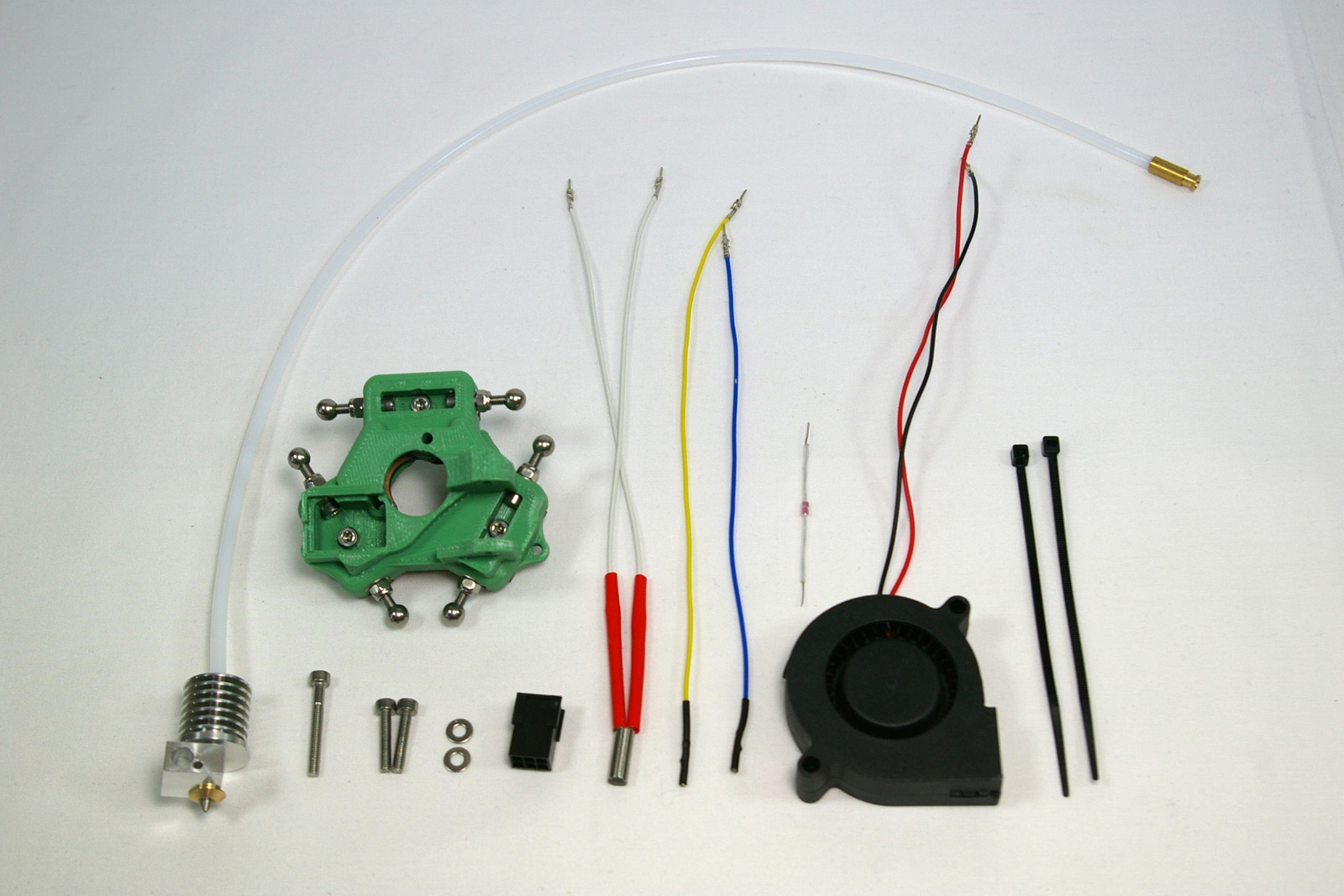 |
|
| Effector assembly | 1 | Assembled | ||
| 112 | M3x25mm cap head screw | 1 | Fastener | |
| 257 | M3x12mm cap head screw | 2 | Fastener | |
| 212 | M3 plain washer | 2 | Fastener | |
| 368 | 3×2 Female Housing (3020-06) | 1 | Hot end | |
| 662 | Cartridge heater 19v | 1 | Hot end | |
| 433 | Thermistor wiring -160mm | 2 | Hot end | |
| 430 | Thermistor (insulated) | 1 | Hot end | |
| 1194 | 50mm blower fan – 160mm crimped | 1 | Electronics | |
| 133 | Cable ties 2mm | 2 | Electronics |
| Pull the thermistor through the heater block.
If you use pliers, use them on the PTFE heatshrink, NOT on the metal legs of the thermistor; you are likely to break the thermistor. Ensure the thermistor bead is seated centrally inside the heater block. |
 |
| Push the hot end into the effector, orientated as shown. This may require a small amount of trimming of the printed effector part, but it is supposed to be a close fit. Do not trim the MDF effector plate; the hot end has a flange that sits on this. Bend the thermistor leg around the heater block; this ensures it can’t fall out. If the nozzle comes loose in the heatsink, taken the hot end out, tighten, and put it back in again. | 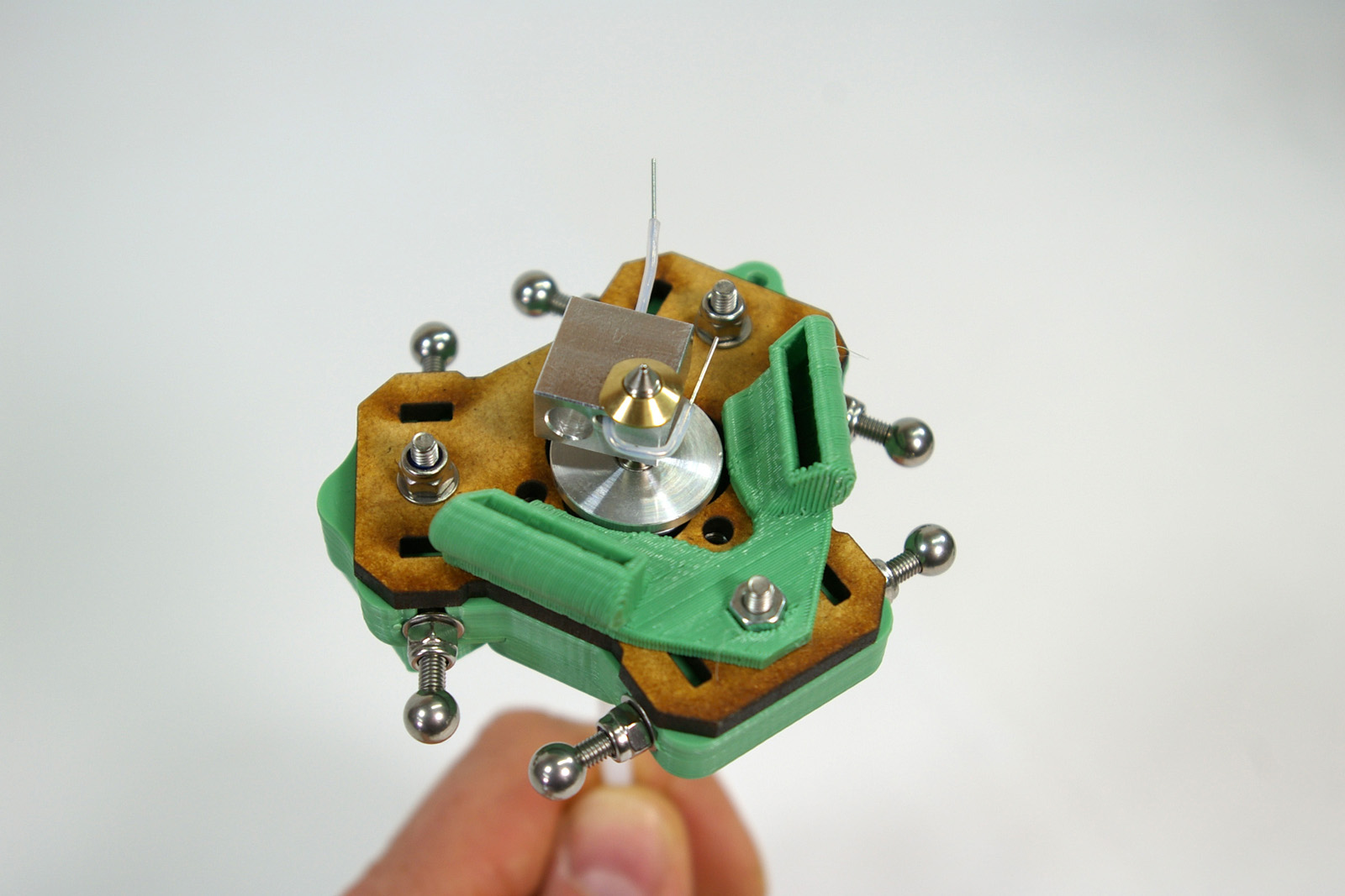 |
| This picture shows the lower flange of the heatsink sitting on the MDF effector plate. | 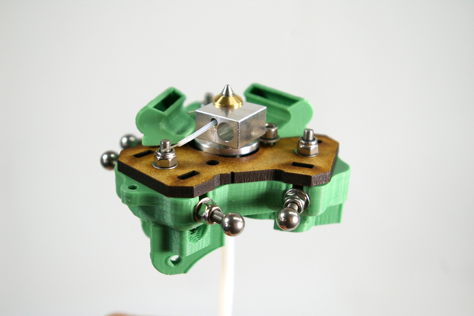 |
| Secure the hot end in place using the two M3x12mm cap head screws and M3 washers as shown. If your kit has more than one M3 washer diameter, use the largest for this. Take care to orient the heater block without loosening the nozzle in the heatsink, before tightening the M3 nuts. It is very important that the screw heads do not touch the heater block; it should be as far as possible from the nearest one. | 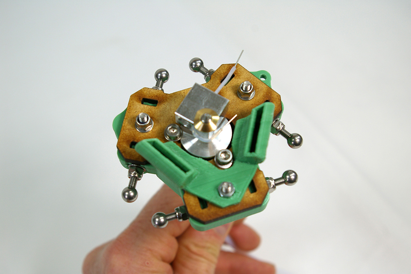 |
Adding the Heater, Thermistor and Fan
| Connect the thermistor wires to the thermistor, and push the heater cartridge into the larger hole in the heater block. All wires should come out the same way. | 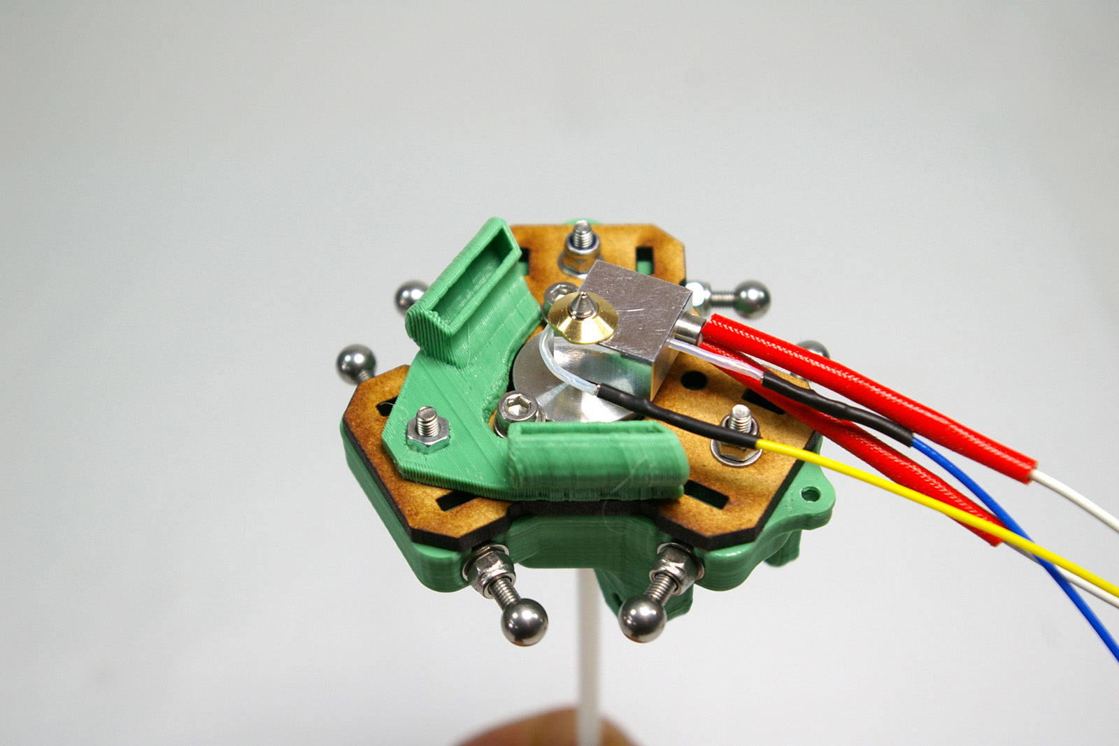 |
| Fit the fan into the printed effector. It should be a snug fit. Using the M3x25mm cap head screw, fasten it in place. This self taps into the printed part.
Fisher kits are shipped with either 19V or 24V fans, and Fisher runs on 19V. We have thoroughly tested the 24V fans we ship to ensure they produce just as good cooling with the 19V supply as the 19V ones do. |
 |
| Secure the fan and hot end wires with the cable ties. Make sure the thermistor and heater cartridge are still fully inserted in the heater block. Try to cable tie the wires to keep them as close in to the effector as possible. | 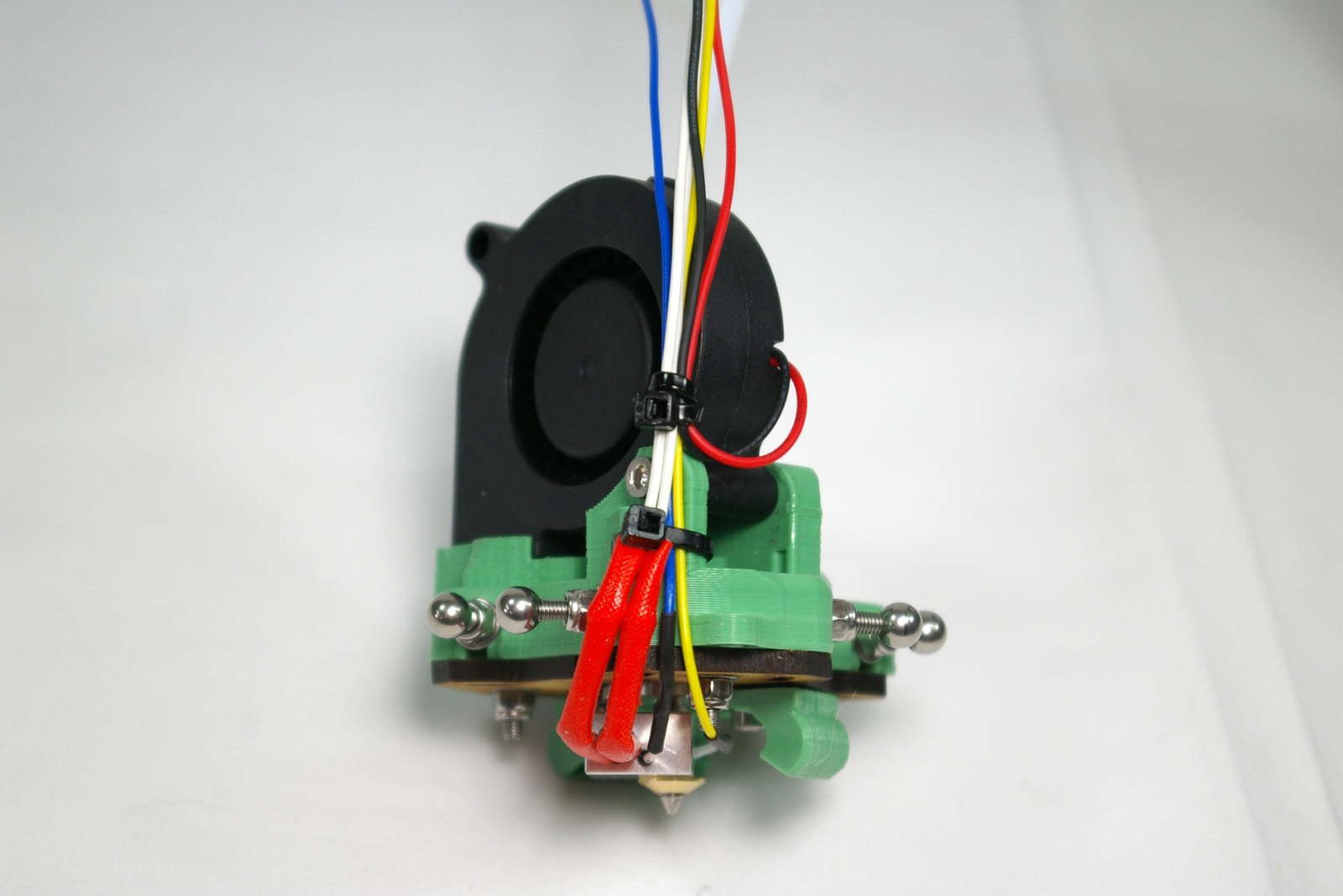 |
Hot End Wiring
| CAUTION! The next step describes wiring up the hot end connector. GREAT CARE should be taken doing this. The heater cartridge and the fan wires have 19V running through them ALL THE TIME. The thermistor wires are 3.3V, and connect directly to the Arduino chip on the Duet controller board. If you incorrectly wire the plug, a short circuit between the thermistor wires and any of the other wires MAY DESTROY YOUR DUET! |
Wiring diagram
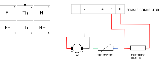
| Put the pins on the ends of the wires into the six-way female socket. The wiring diagram, above, is looking into the back of the socket, where you insert the crimps. The little black rectangle is the locking tab, and the housing has small embossed ‘1’ and ‘6’ numbers on it, so you can orientate it as the diagram. The pins are crimped on one side, and smooth on the other. The smooth sides go downwards in the diagram. | 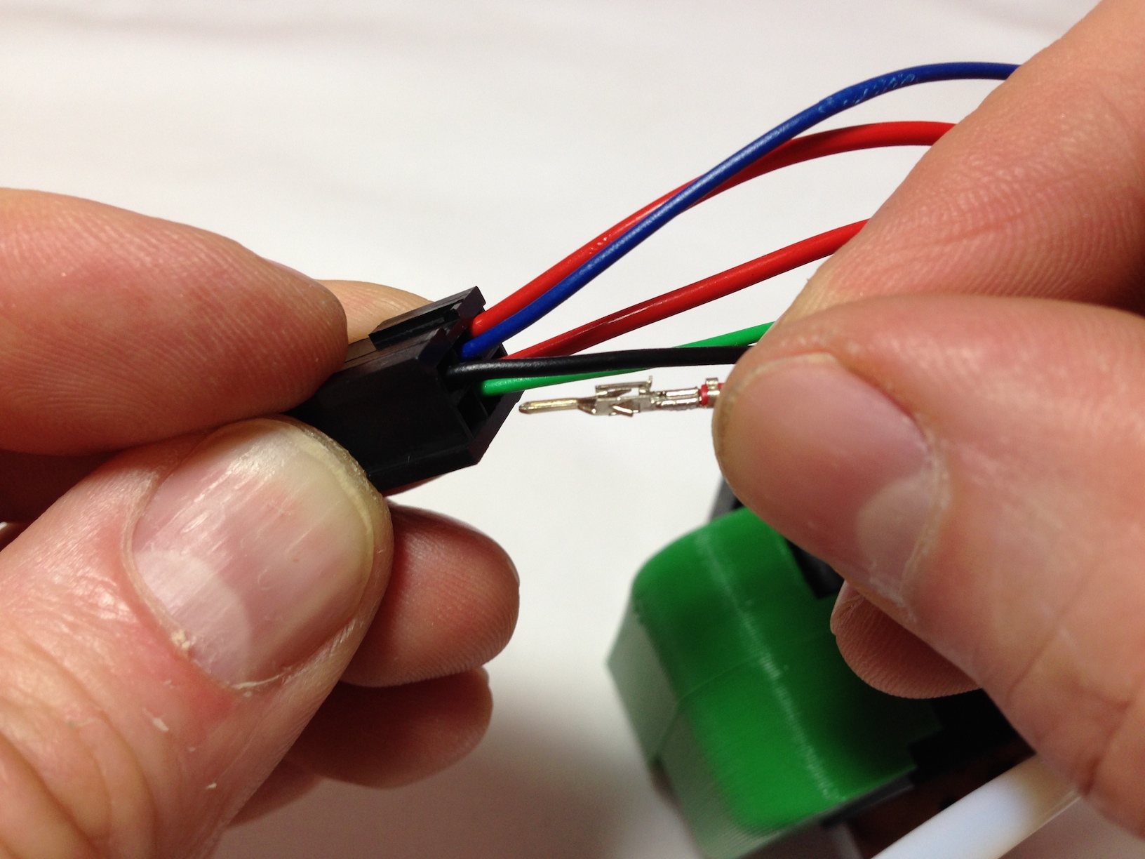 |
| Neither the thermistor nor the heater cartridge have a polarity so it doesn’t matter which way round their wires go. (Though the H+ and H- are the way that the machine will apply power – hence the labels.) Make sure to get the polarity of the fan right. This picture shows one of the fan wires being put into the housing, but it is not fully in yet; you can’t see the crimp easily when it is. | 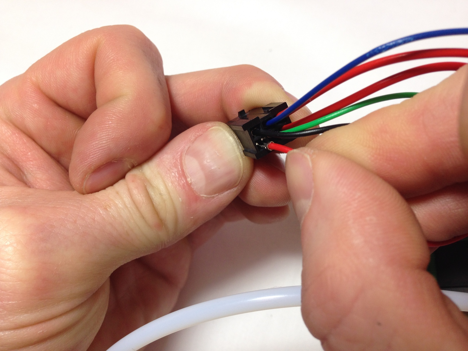 |
| Check that the pins are all the same depth into the housing. The pins are very difficult to remove without damaging them, so check twice, plug in once! They should click into place, and then shouldn’t easily push further through, or pull back out. | 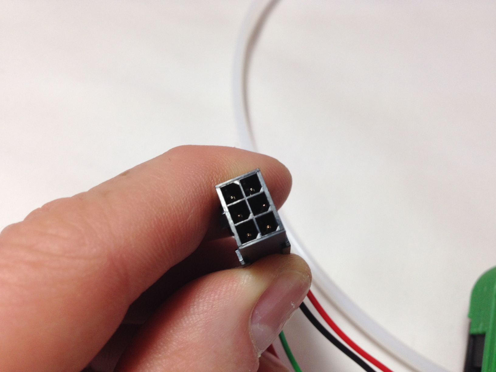 |
Wire Colours Related to Hot End Wiring Loom
Note below that the colours ether side of the connector do not all match up. This is because of backwards compatibility with other designs. Make sure you do what it says in this table.
| Wiring loom | Hot end wires |
| 1 Yellow | Red FAN wire (+19V) |
| 2 White | Black FAN wire (ground) |
| 3 Green | Yellow Thermistor wire (3.3V) |
| 4 Blue | Blue Thermistor wire (3.3V) |
| 5 Purple | Orange or white heater wire (+19V) |
| 5 Black | |
| 6 Red | Orange or white heater wire (ground) |
| 6 Brown |
| You can check the wire order by comparing it to the end of the hot end loom, which the hot end plugs into. | 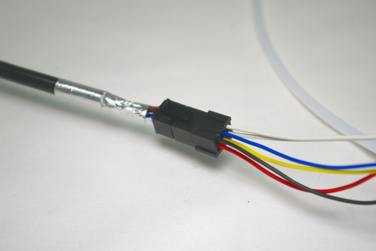 |
Mounting the Effector
| If you wish you may put a little silicone grease on the six effector balls to lubricate them and the rods. But don’t use mineral-oil based grease as this may damage the rods.
Orientate the effector so the fan is facing the open side of the printer. As you did when connecting the rods to the carriages, gently prise the rod ends apart, and slip them over the balls of the effector. Tighten the grip of the rods on the stainless steel balls, by tightening the M3x8mm cap head screws on the rods. |
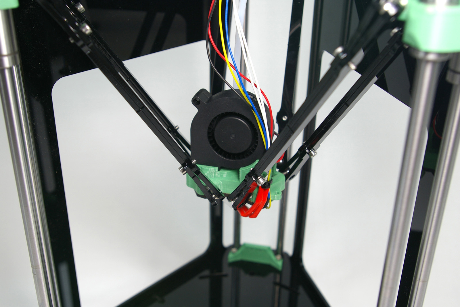 |
| The printer so far.
(The image shows a terminator on the free end of the PTFE tube. This is no longer needed.) |
 |
Back – Extruder Drive Next – Electronics