
Build Instructions – Base Assembly – Tower Assembly – Panels and Rods – Effector Assembly – Extruder Drive
Hot End Assembly – Electronics – Bed, Top Plate and Belts – Commissioning – Printing – Troubleshooting
This page describes the older Duet 0.6 electronics shipped with kits before August 2019. If you have a more recent kit it will have Duet 2 Maestro electronics, which is described on this page.
Goal
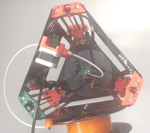
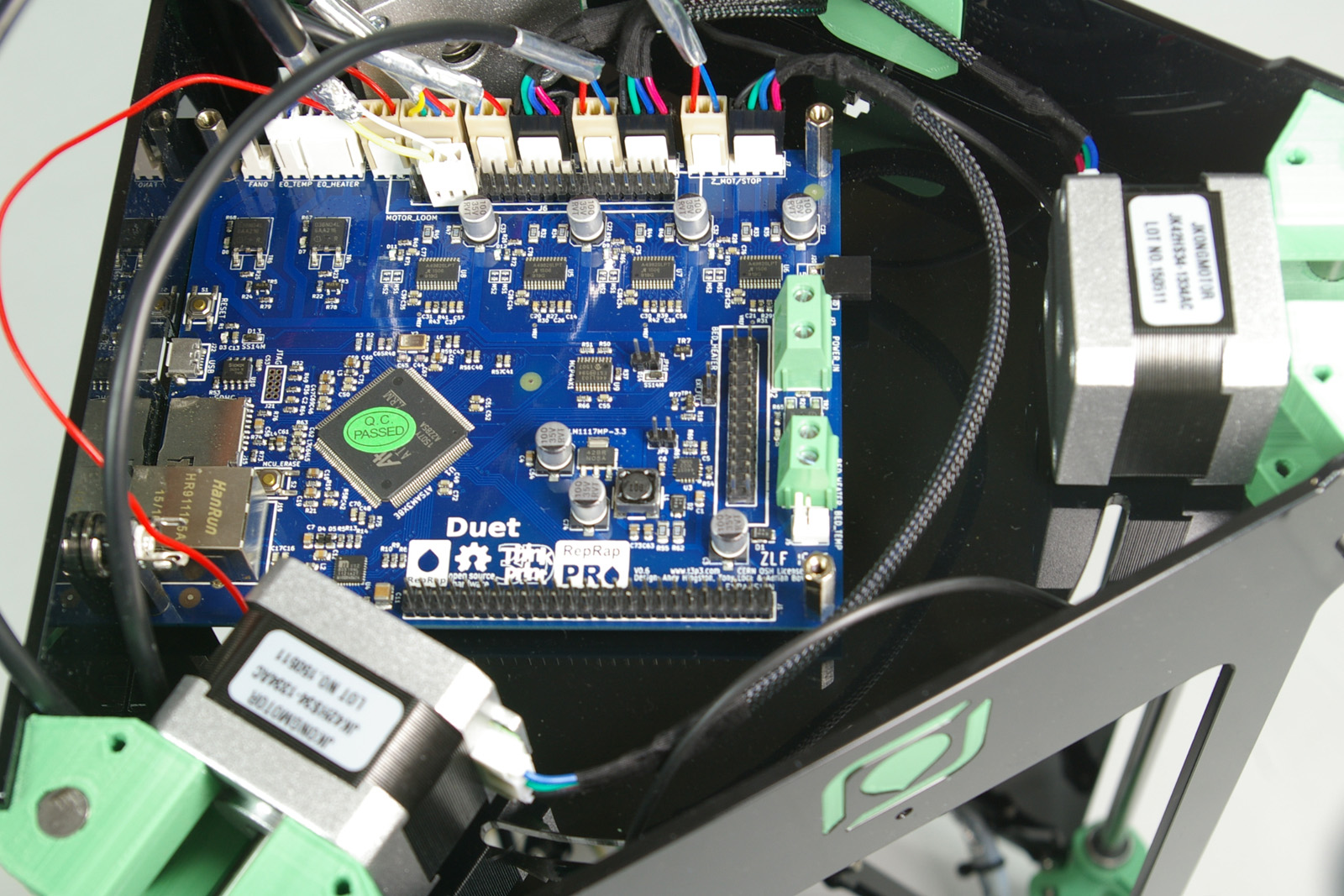
By the end of this section, you will have wired up the electronics and installed it in the printer frame (view from underneath).
Side Panel Wiring
You will need the following parts:
| # | Component | Qty | Type | |
| 1303 | Side Panel | 1 | Laser cut | 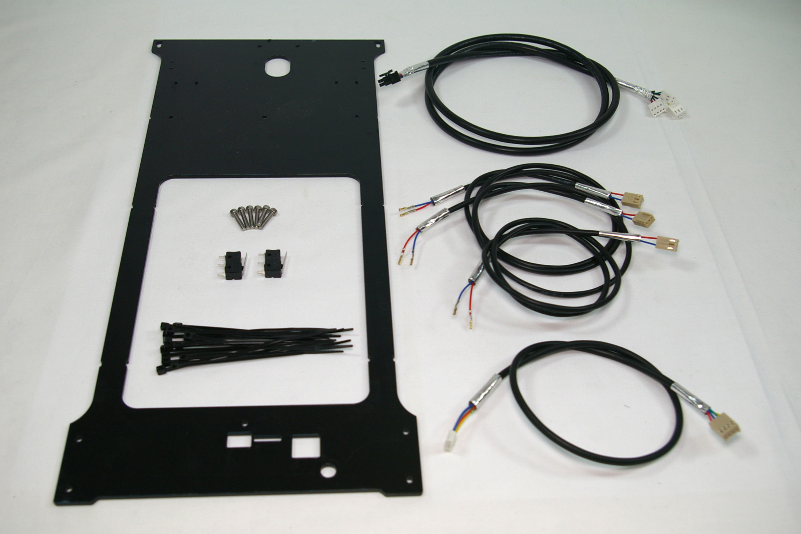 |
| 242 | M3x16mm cap head screw | 6 | Fastener | |
| 185 | Microswitch | 2 | Electronics | |
| 133 | Cable ties 2mm | as needed | Electronics | |
| 585 | Hot end loom – 1190mm | 1 | Wiring | |
| 1198 | End stop loom – 500mm | 1 | Wiring | |
| 552.1 | End stop loom – 600mm | 1 | Wiring | |
| 1199 | End stop loom – 800mm | 1 | Wiring | |
| 789 | Motor wiring loom – 500mm | 1 | Wiring |
| Remove the protective film from the acrylic panel. | 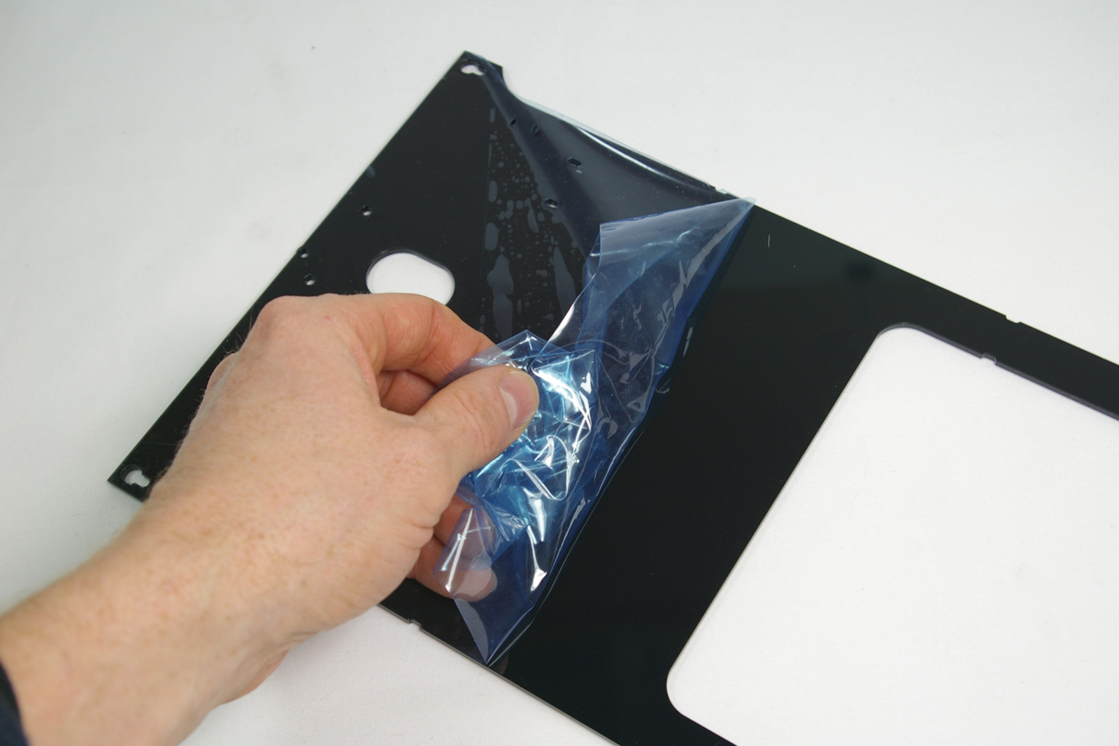 |
| The microswitches fit to the inside of the panel. Note the orientation of the bottom of the panel; this fits around the Duet electronics. | 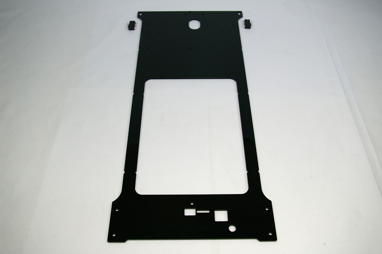 |
| Fit the microswitches with cable ties, as you did with the first microswitch. Make sure the cable tie end is towards the top of the panel. | 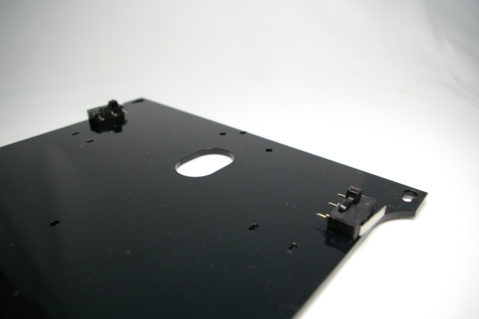 |
| The endstop looms have two wires, and there are three different lengths of looms. | 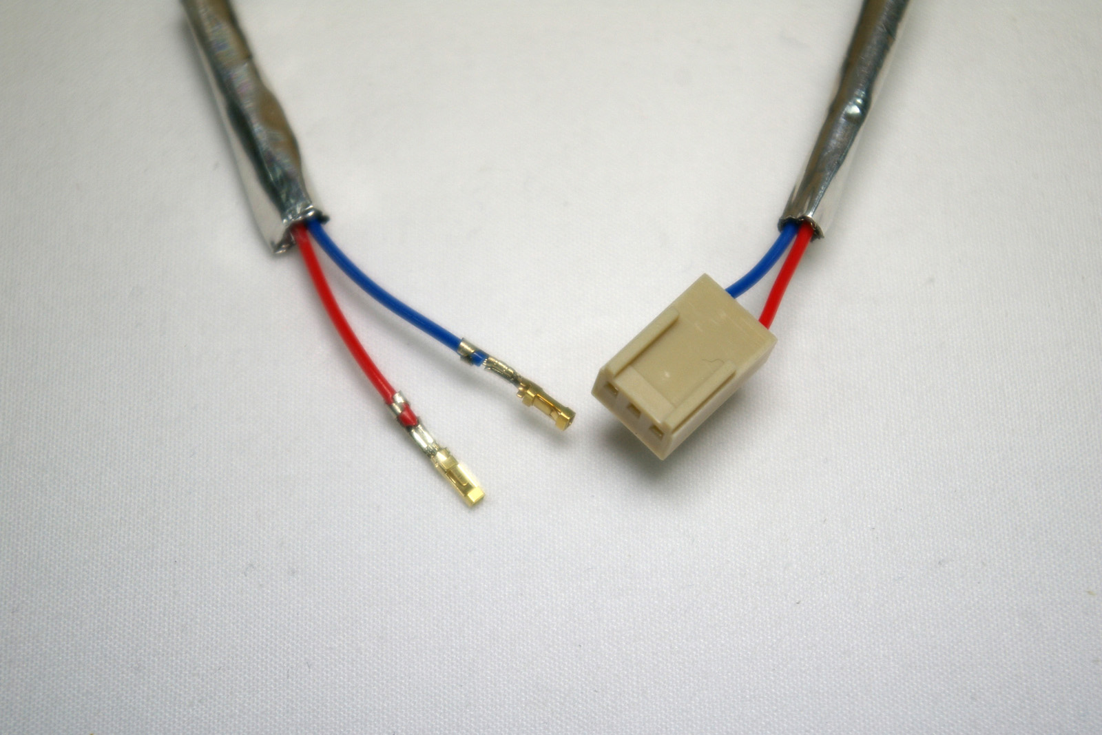 |
| The hot end loom has eight wires. | 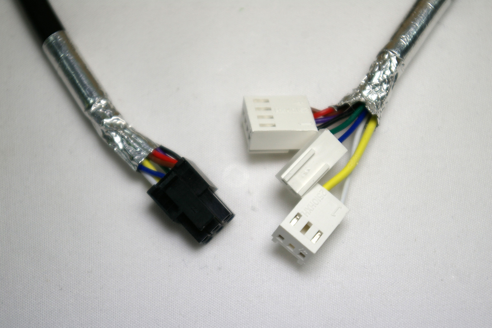 |
| The extruder motor wire has four wires. This is the longest motor wire (500mm). | 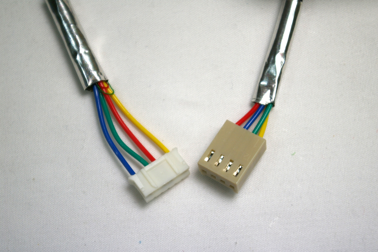 |
| Mount the shortest endstop loom (500mm), the hot end loom and the extruder motor loom on the left side. The other two endstop looms go on the right. | 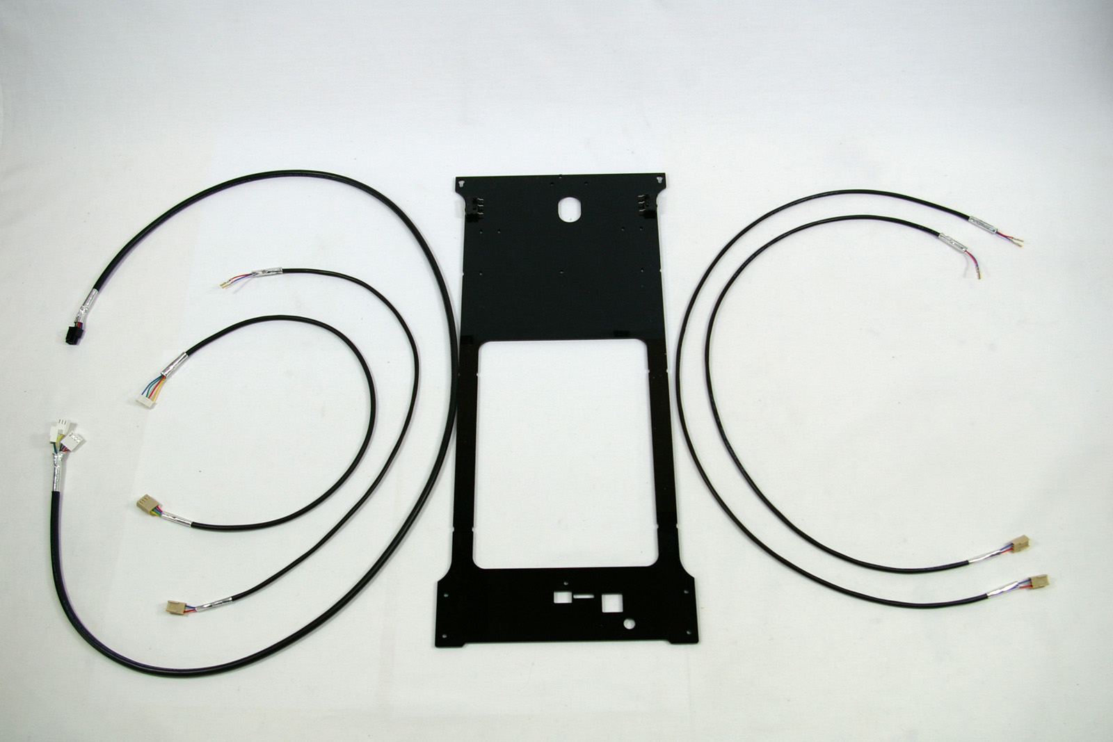 |
| Left side: Attach the endstop loom to the microswitch on the left hand side. Put the crimps on the outside tabs of the microswitch, NOT the middle one. Polarity is not important. Try not to bend the crimps on the microswitch tabs, or they will become loose. | 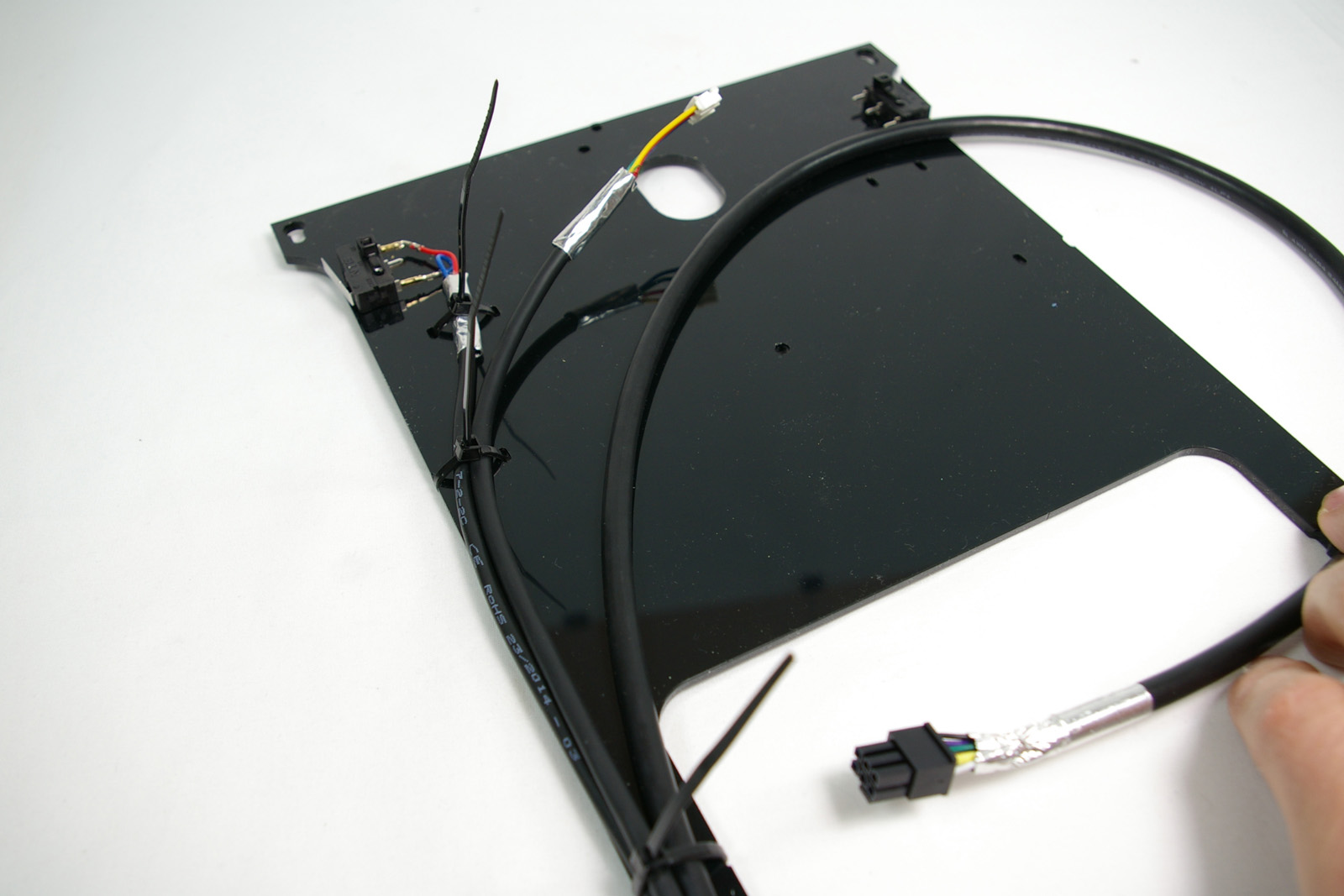 |
| Fasten the endstop loom in the top cable tie, the endstop and the extruder loom in the next one down, and all three looms in the rest of the cable ties. Don’t fully tighten the cable ties yet, so you can adjust the wire position. | 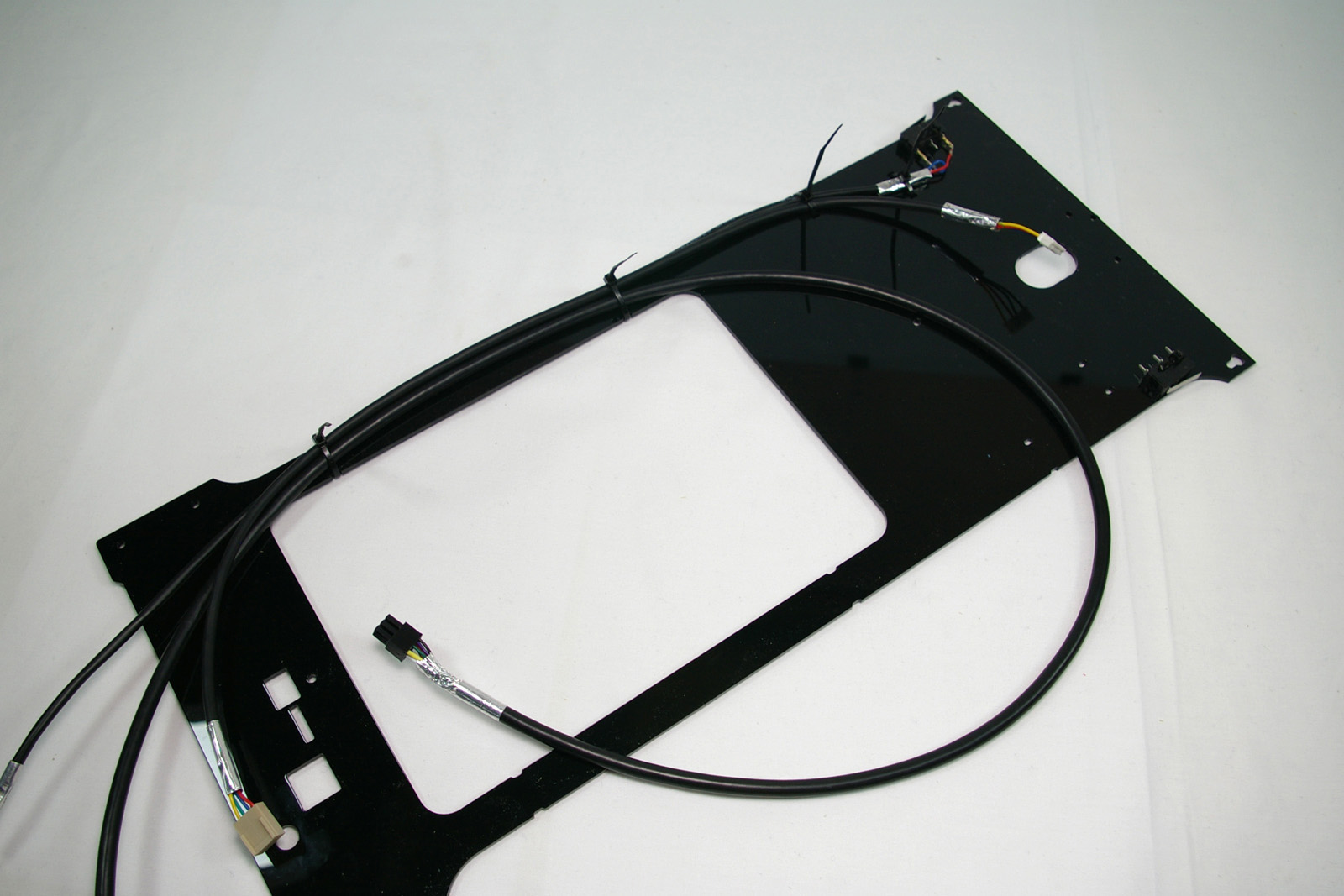 |
| Right side: connect the shorter endstop loom (600mm) to the microswitch. | 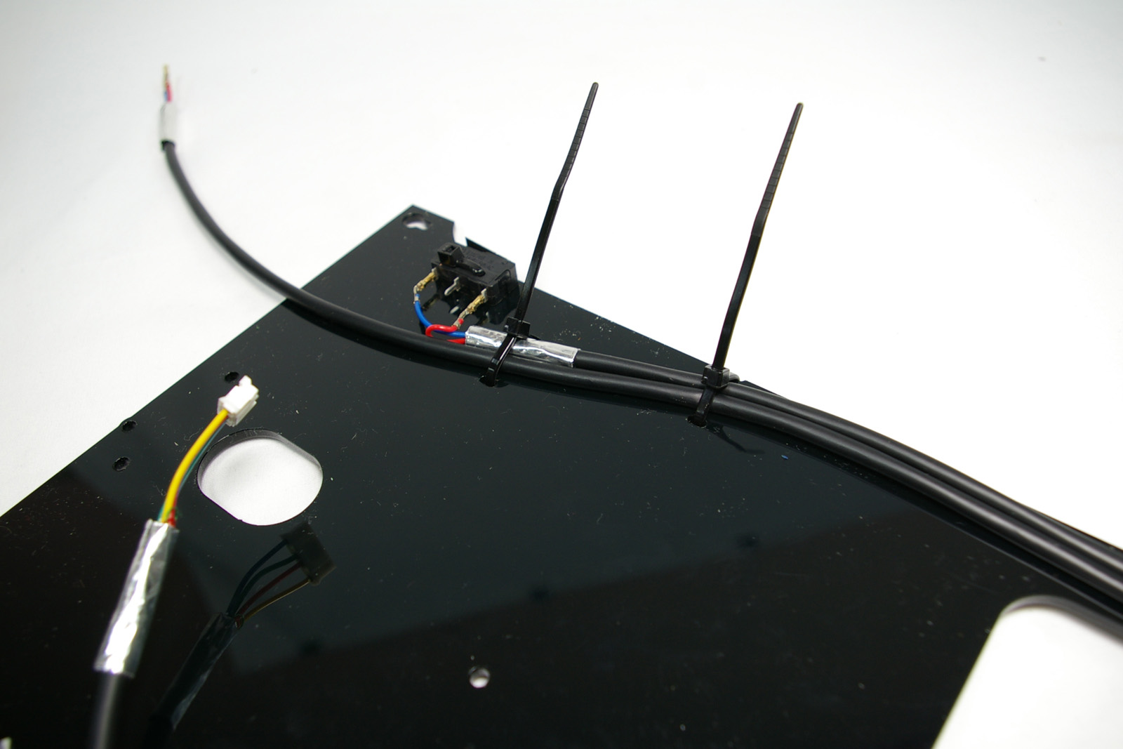 |
| Cable tie both wires in all of the positions. | 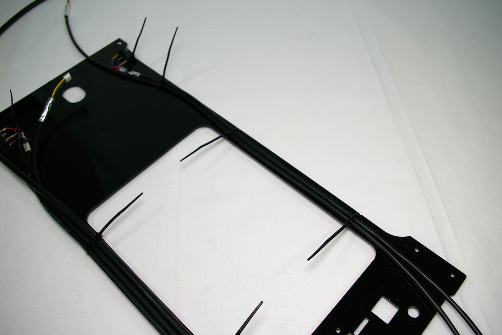 |
| Attach the extuder drive to the panel, using two M3x12mm cap head screws from the outside. Connect the extruder motor loom to the extruder motor. | 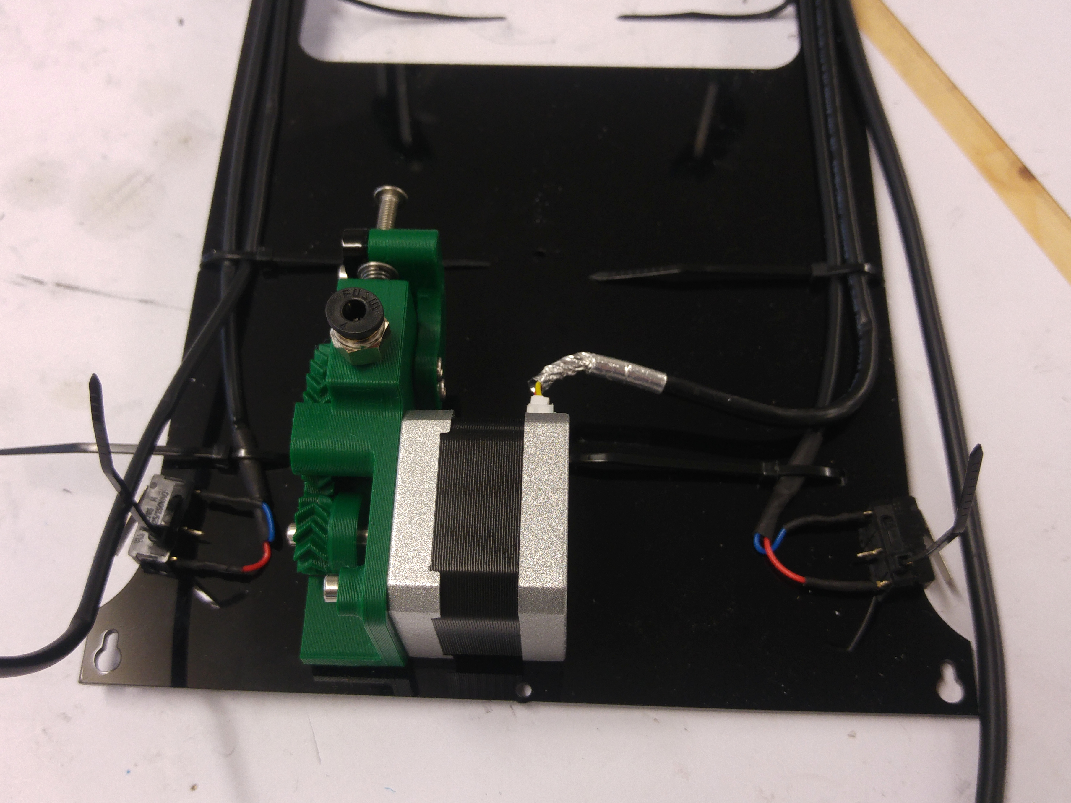 |
Fit the Panel and Connect
| As with the other panels, lift the printer up off the surface, and fit the top of the panel onto the screws in the idler printed part. | 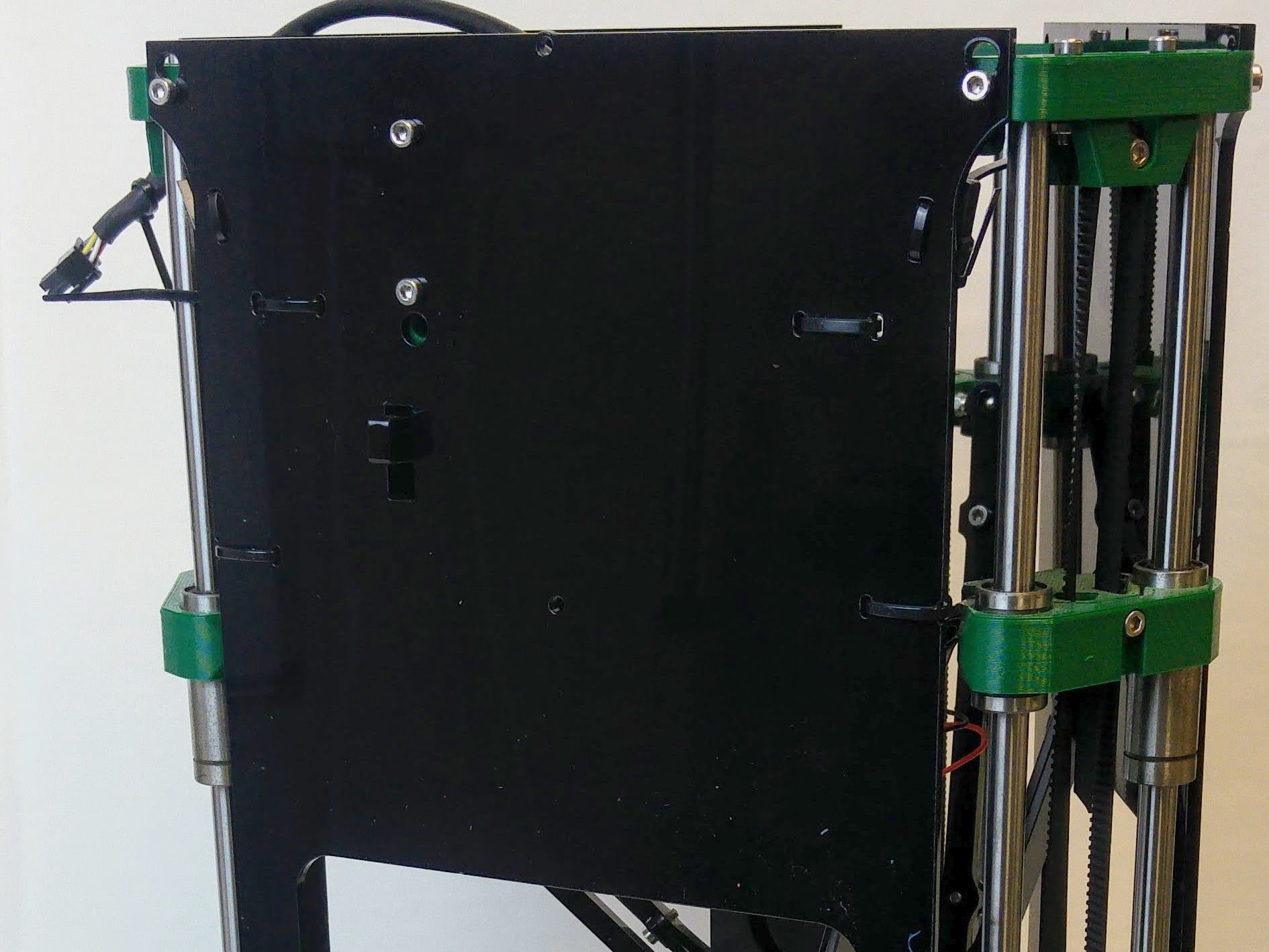 |
| Line up the bottom with the holes in the motor mounts, and fasten with four M3x16mm cap head screws. Make sure the wiring looms fit into the slots in the base plate. | 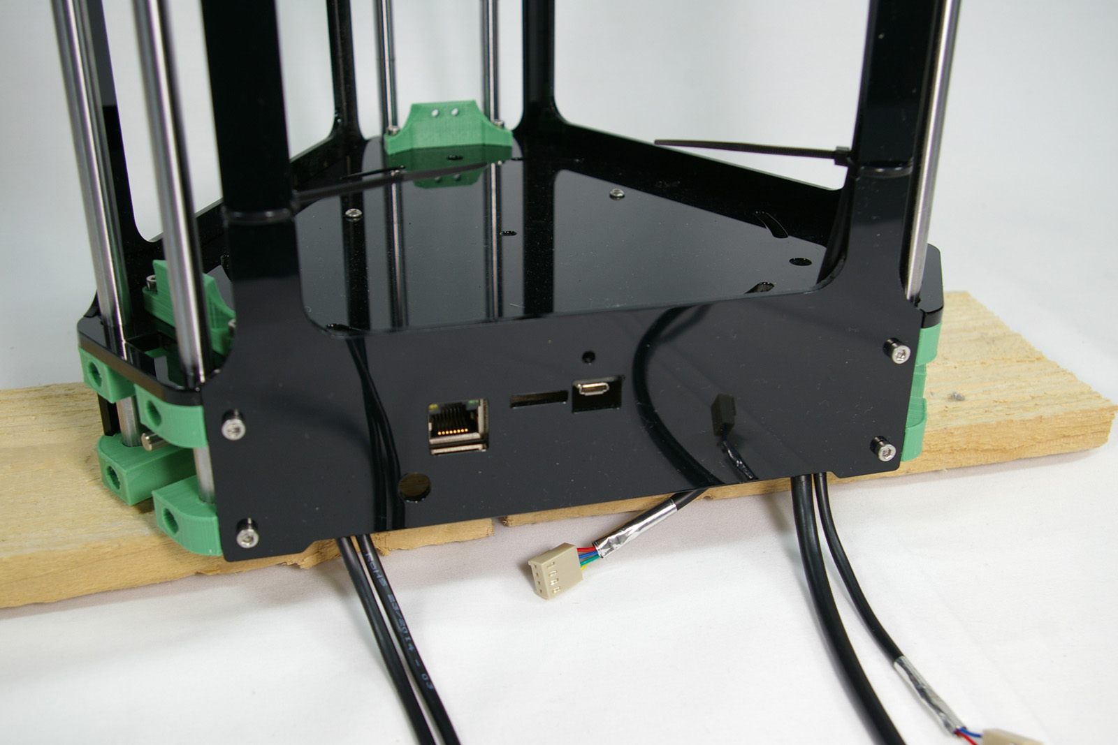 |
| Connect the Bowden tube to the extruder. Push the bowden tube into the pneumatic fitting. | 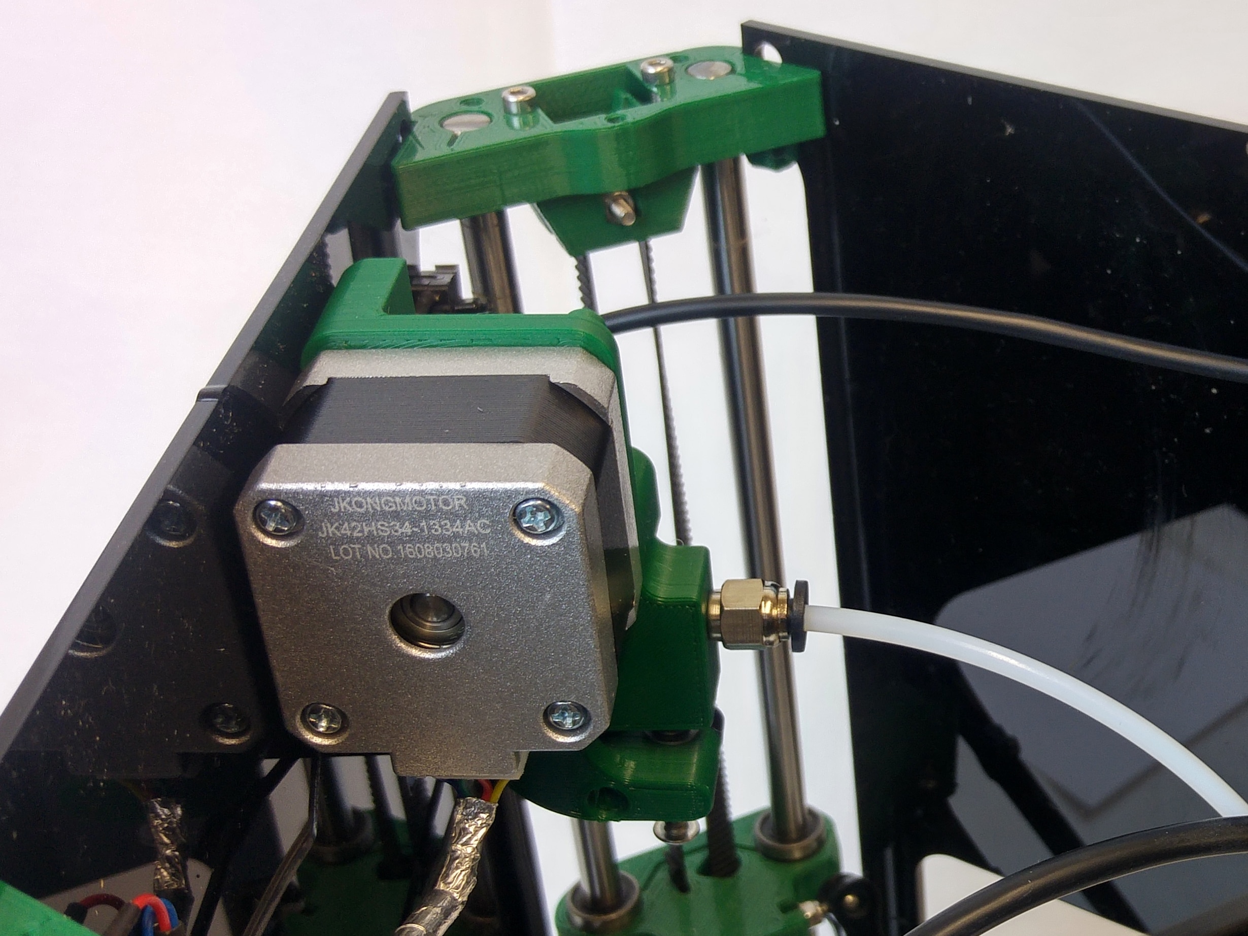 |
| Position the nozzle of the hot end touching the approximate centre of the bed by hand. This is a top view showing what the Bowden tube length should be like – you want a loop so the hot end is free to move everywhere over the bed without causing a tight bend at either end, but you don’t want it so long that it flaps about.
If you need to, shorten the tube with a sharp blade. Take care to make a right-angled cut. |
 |
| Connect the third microswitch in the same way as the other two, and cable tie it to the panel. | 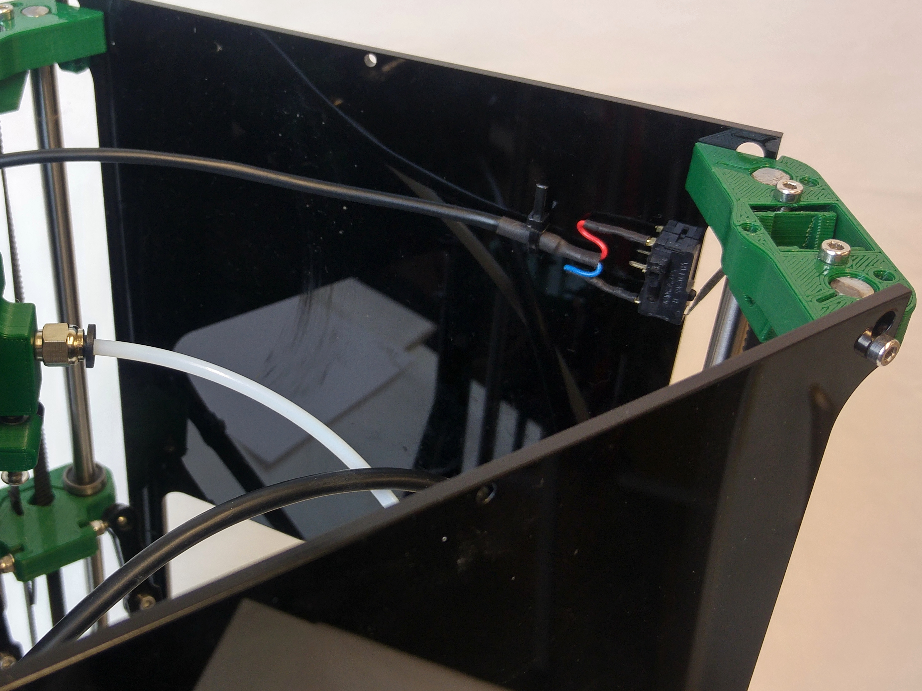 |
| Connect the hot end loom to the hot end. It is useful to cable tie the loom loosely to the Bowden tube, above and below the connector. Check that plugging the connectors together has not pushed any of the crimps partly out of their shells. If it has, use a narrow-bladed screwdriver to push them back. | 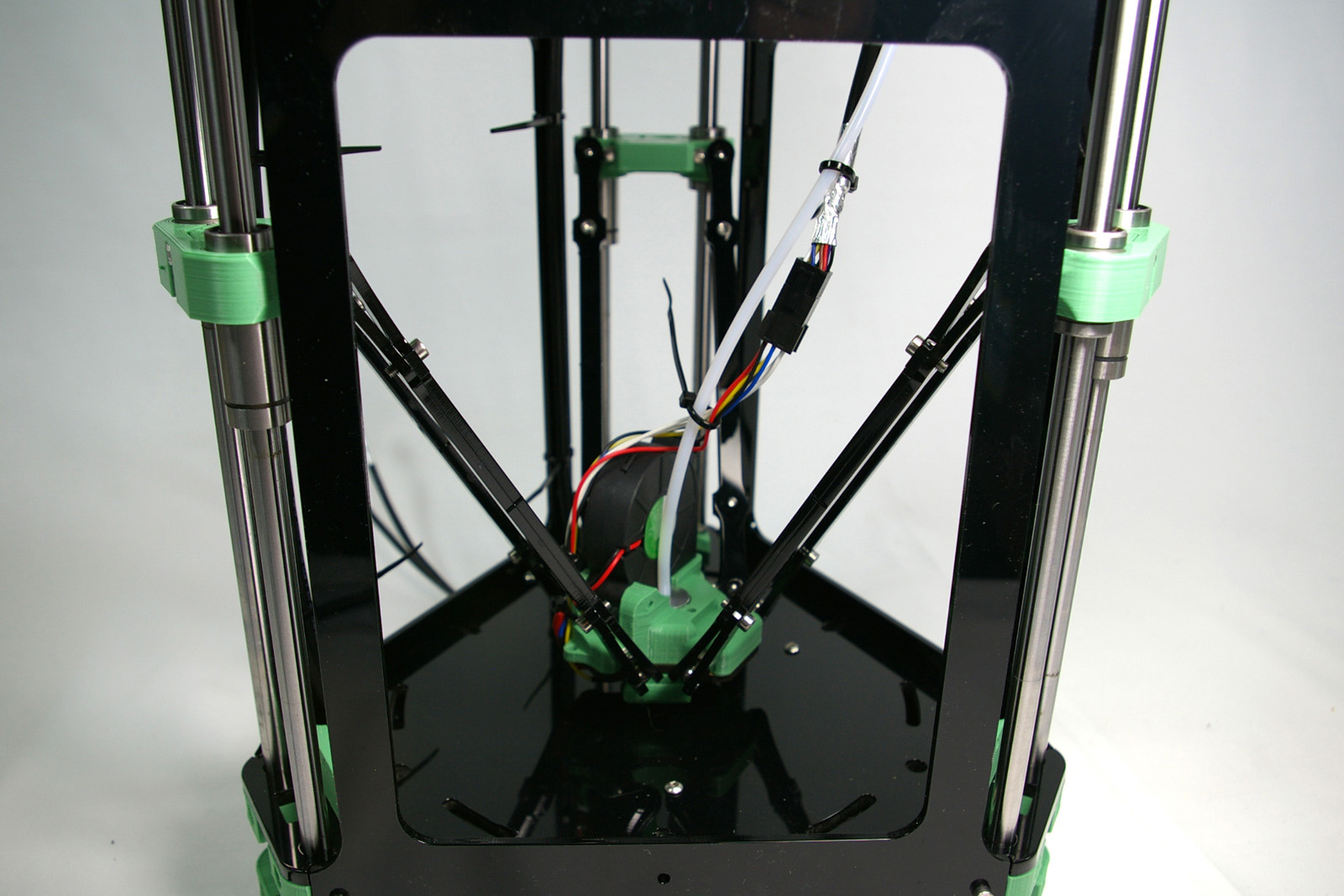 |
| Now adjust the cable lengths until everything is neat, moving the mechanism between the top and bottom to check. The hot end loom and Bowden tube should move together. Try and get a nice loop, so they concertina up as the effector moves up. | 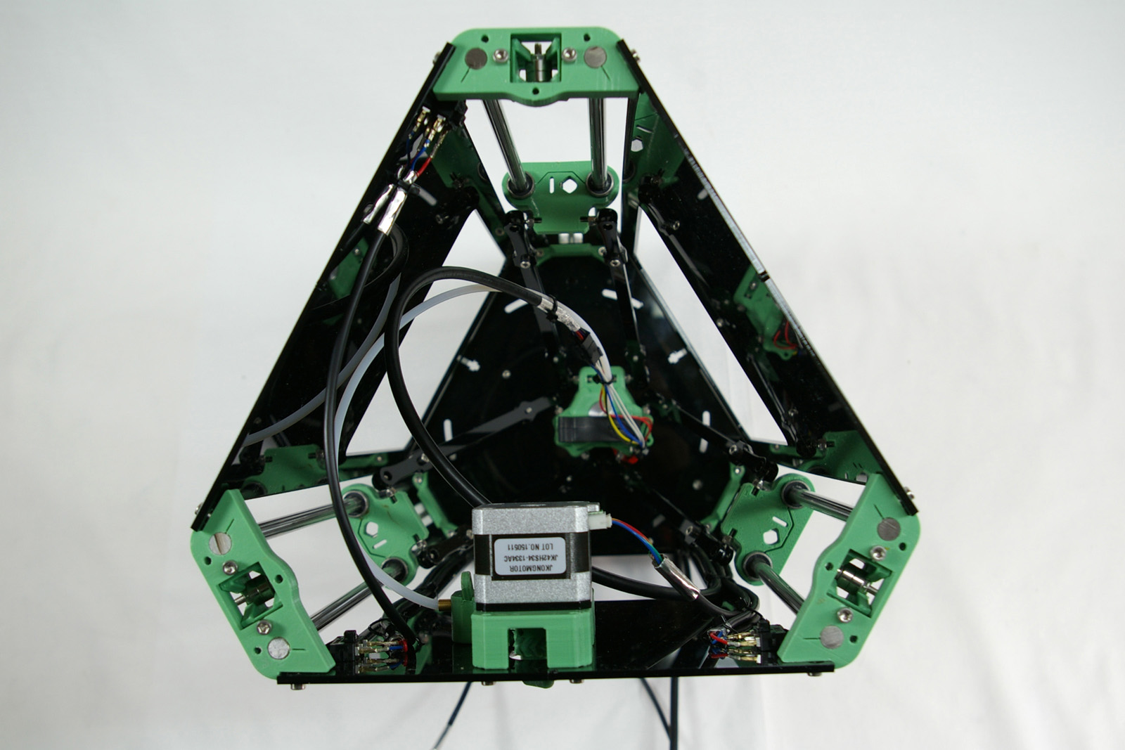 |
| Tighten and trim all of the cable ties. Move the carriages up and down their full range of movement, making sure they don’t catch on anything. Check that the heads of the cable ties don’t get in the way, and that the wiring looms are neat against the side panels. Adjust any cables as needed, and make sure the hot end loom and Bowden tube don’t catch on anything. | 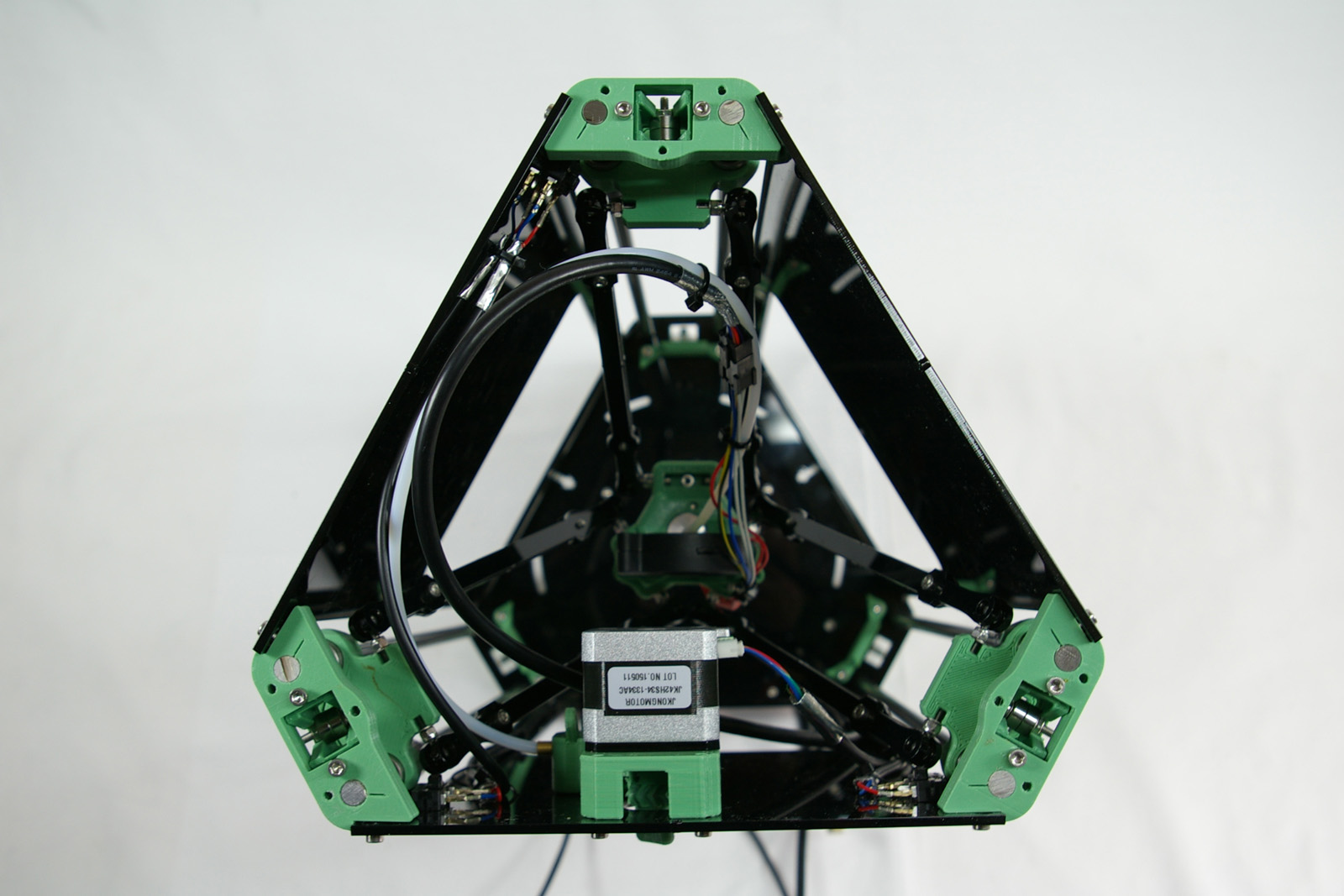 |
Bed Probe Wiring
You will need the following parts:
| # | Component | Qty | Type | |
| 1203 | Bed probe loom | 1 | Wiring | 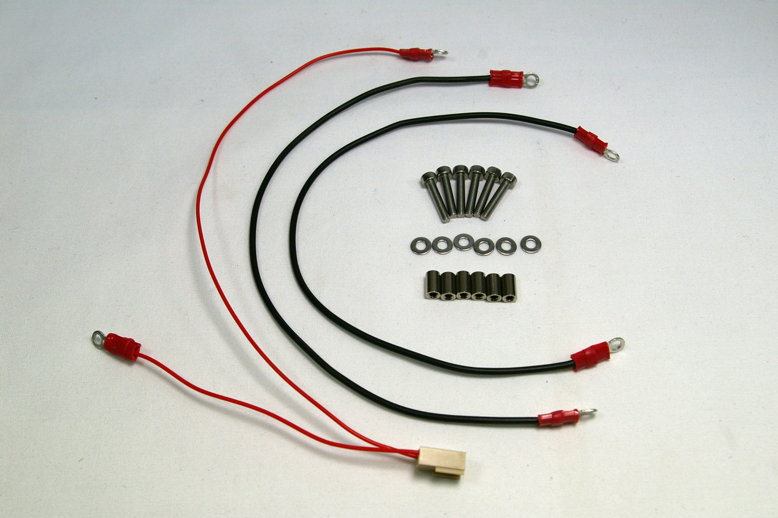 |
| 1202 | Bed probe wire | 2 | Wiring | |
| 257 | M3x12mm cap head screw | 6 | Fastener | |
| 212 | M3 washer | 6 | Fastener | |
| 1253 | M3x8mm spacer | 6 | Hardware |
| Fit the bed probe loom 3-way connector to the E-stop header on the Duet. Push the wires through the slots in the base, as shown. | 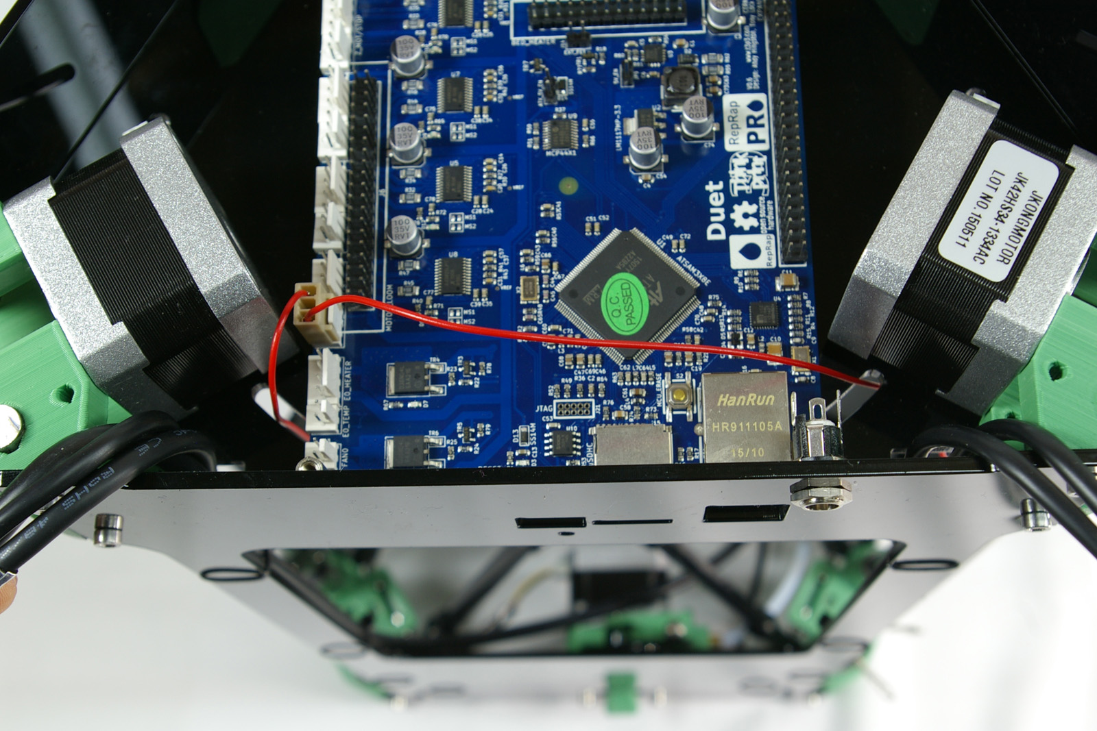 |
| Attach the ring terminals of the bed probe loom and bed probe wires to the bed mounting brackets. For each connection, the order is M3x12mm cap head screw, ring terminal of loom, kinematic mount, M3 washer, round spacer. | 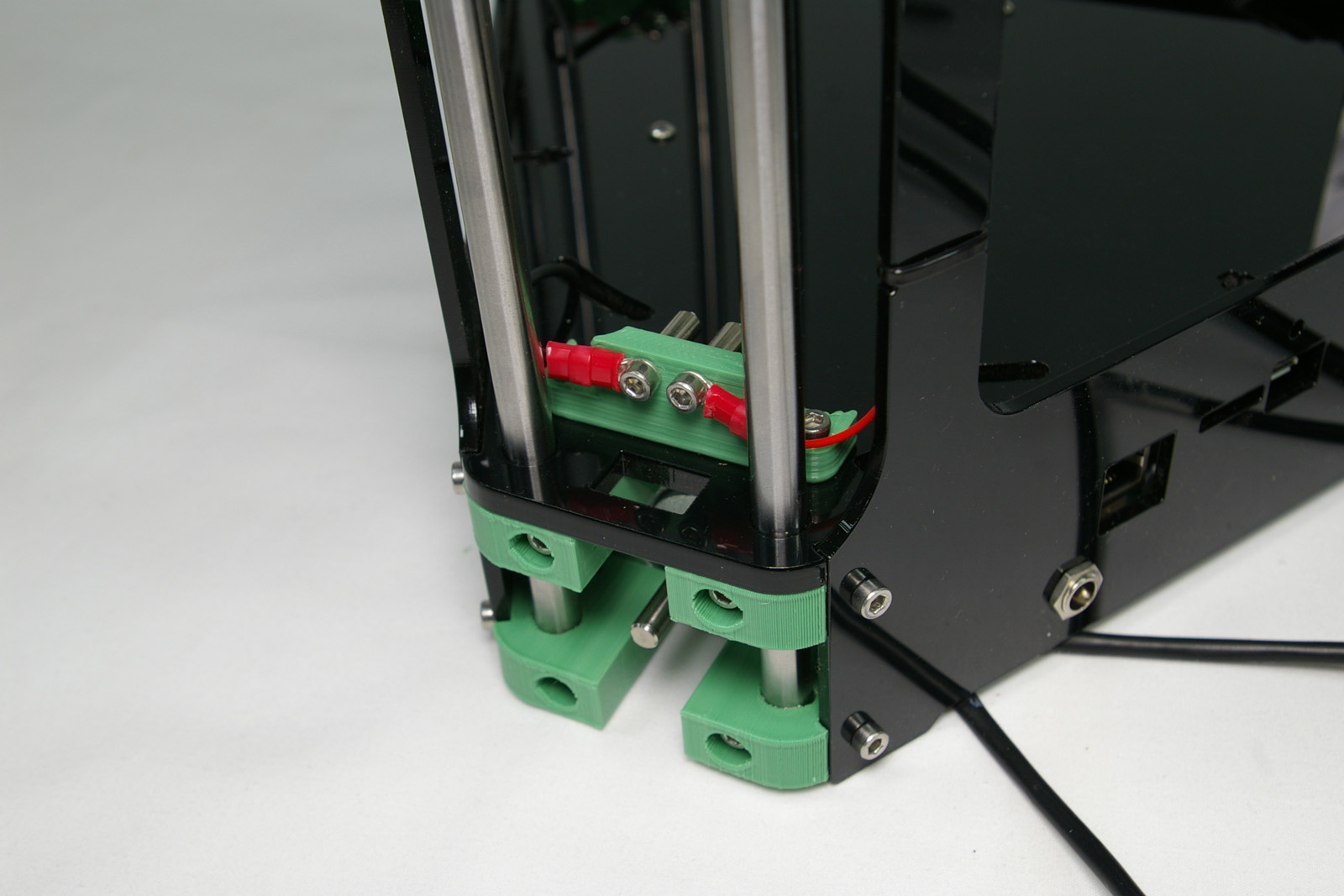 |
| View from the front of the kinematic mount. The bed probe wires run down through the slots and back up again to the next connection. | 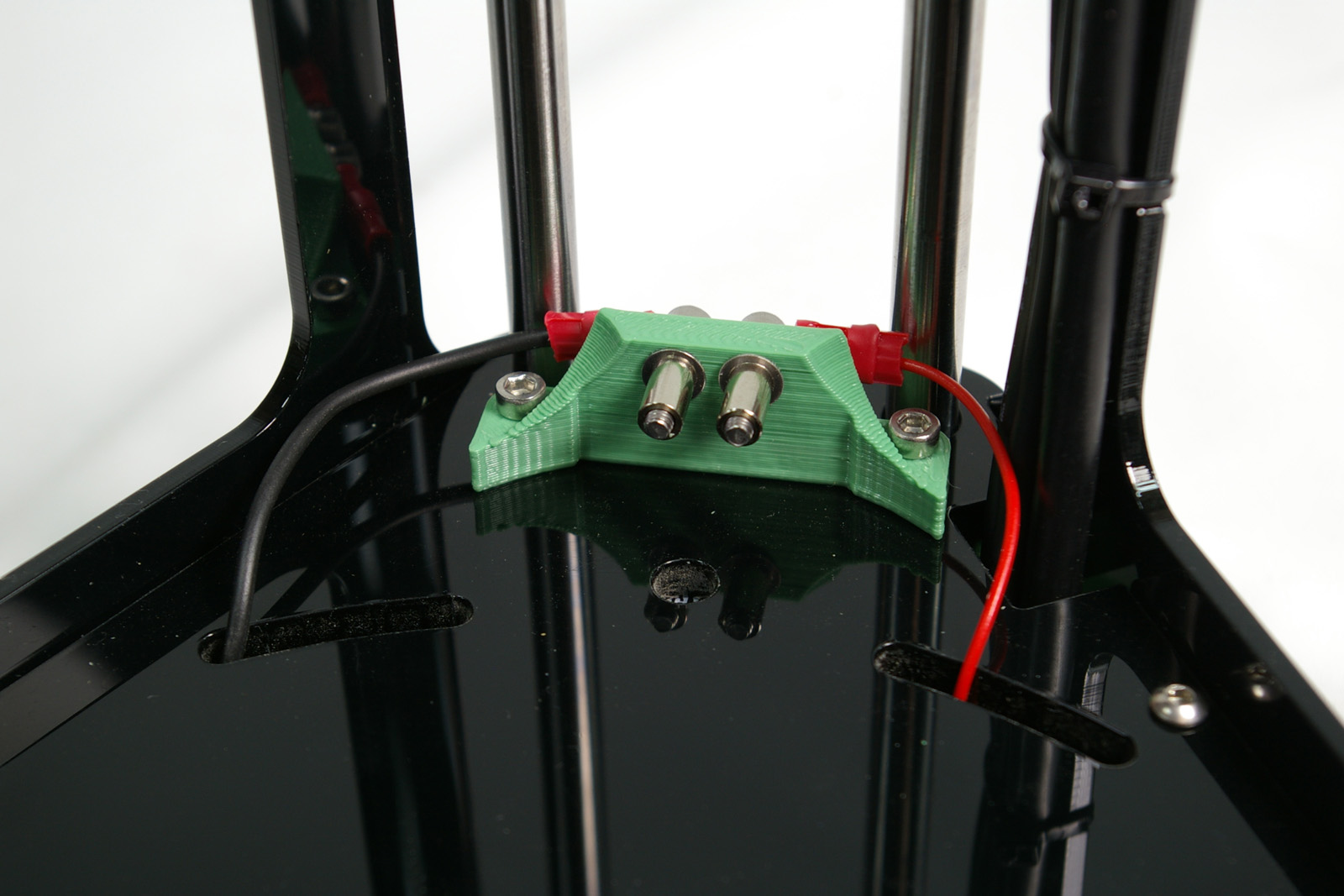 |
| Repeat the above steps for all six connections. The circuit goes around the triangle. The round-headed screws on the print surface will complete the circuit (see later). When the nozzle pushes down on the bed, the circuit is broken. This calibrates the nozzle height. | 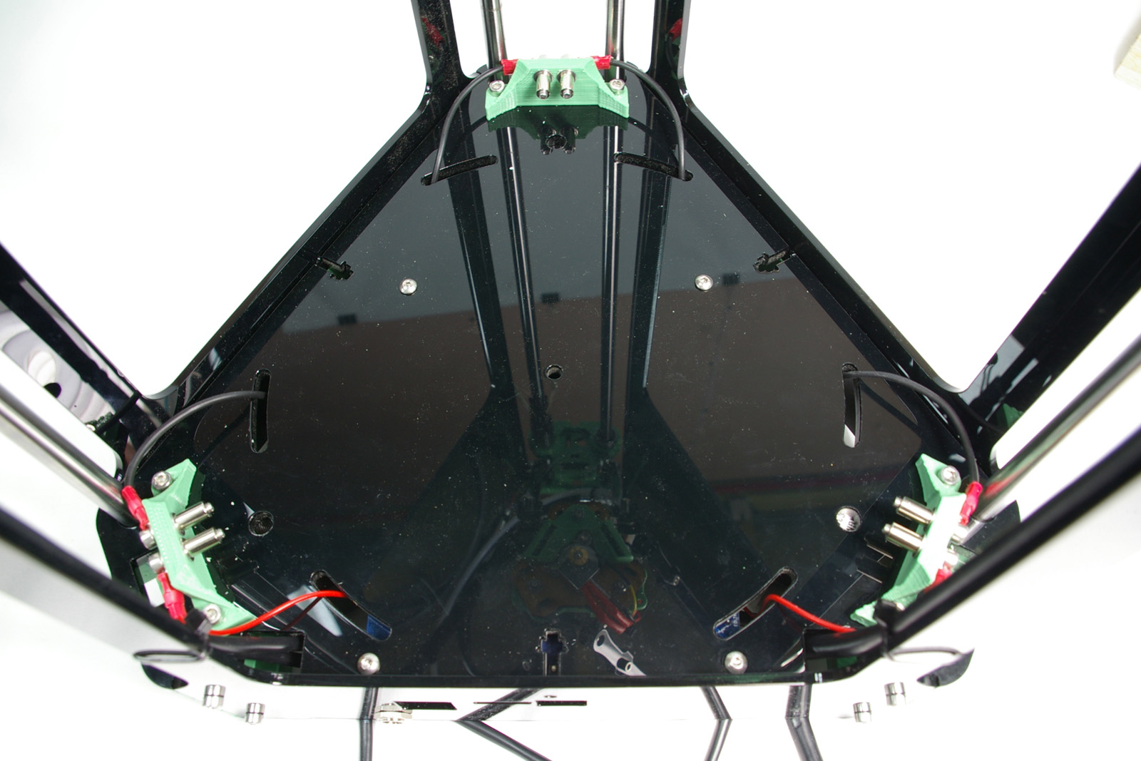 |
Fit the Power Jack
You will need the following parts:
| # | Component | Qty | Type | |
| 193 | Power jack | 1 | Electronics | 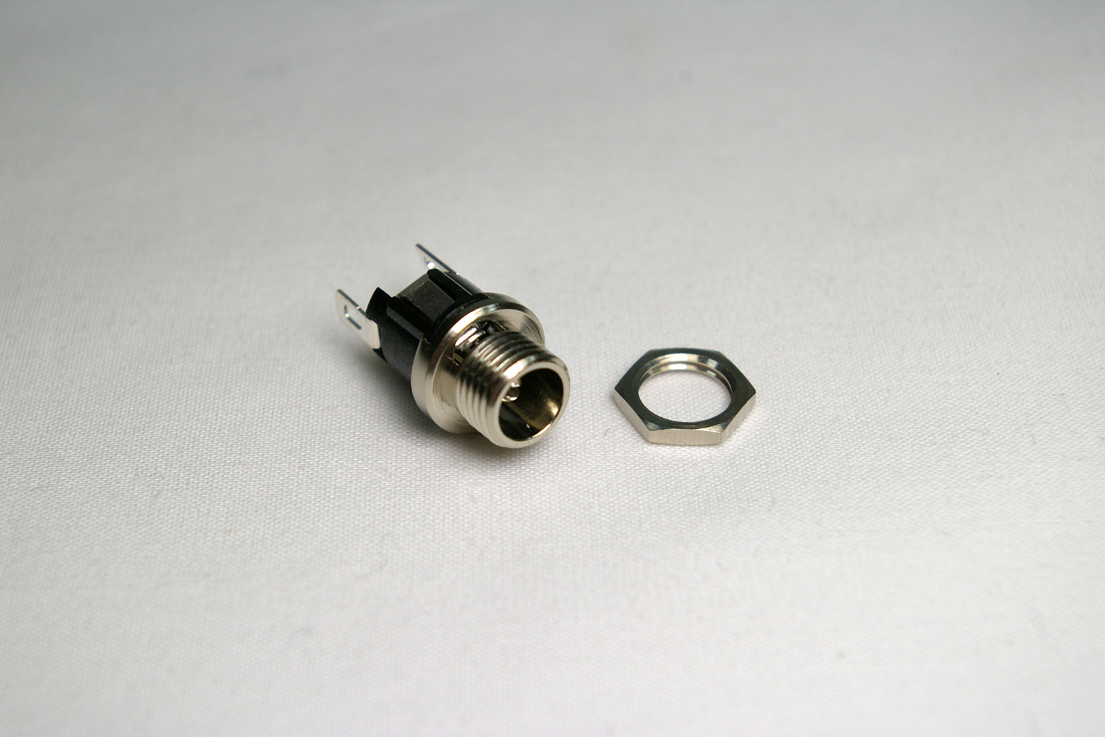 |
| 455 | Power jack nut | 1 | Electronics |
| Turn the printer over. It can rest on it’s top as you connect the wiring. The DC power jack may now be fitted as shown, next to the Ethernet socket. | 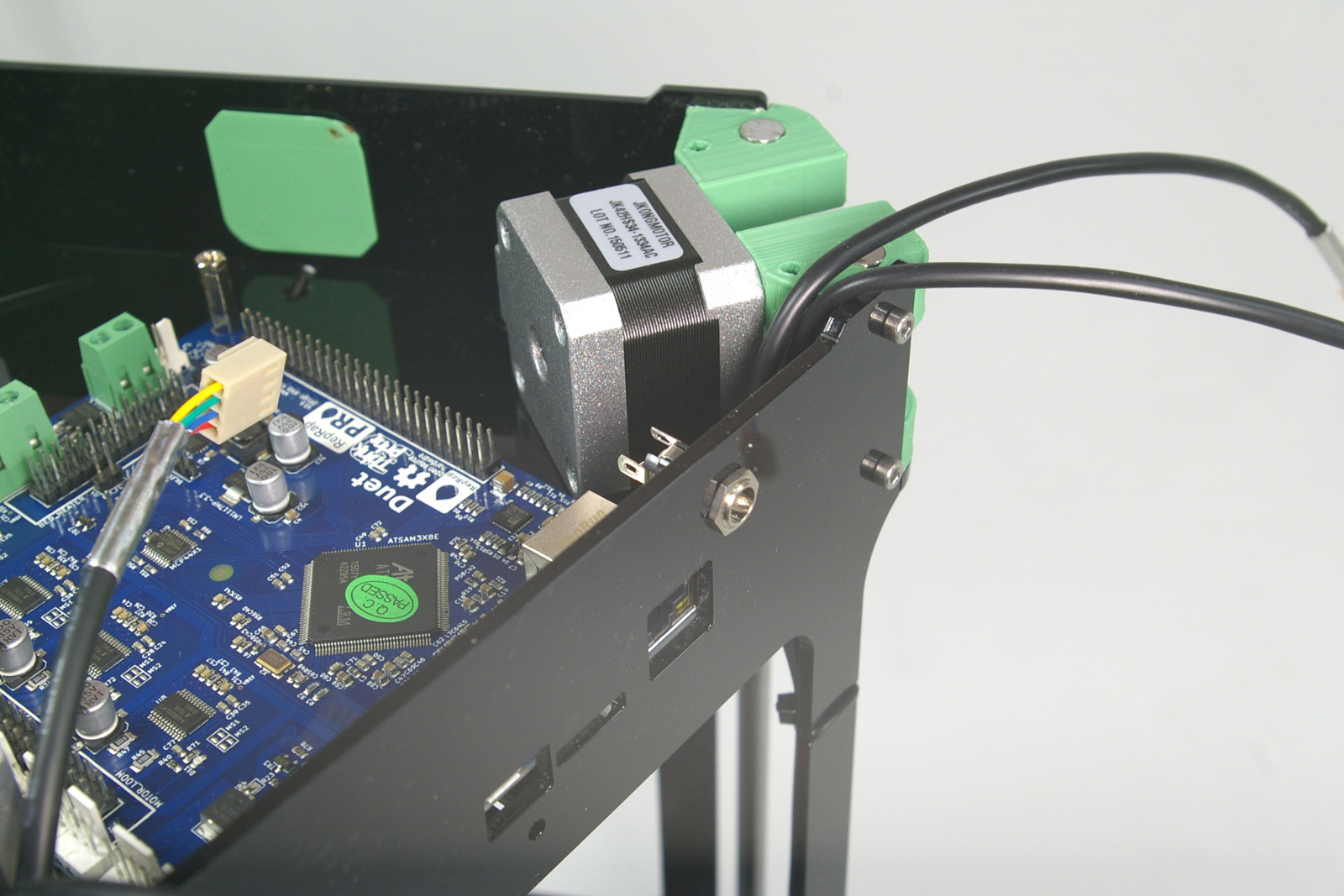 |
Duet Connections
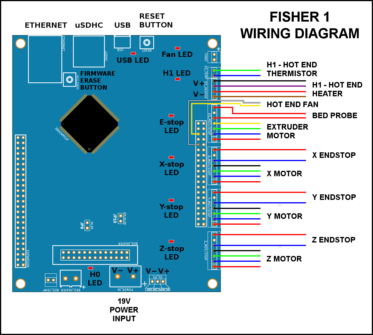
Wiring Diagram
The instructions below show the fitting of the wiring. If in doubt, refer to this wiring diagram.
Duet Wiring Connections
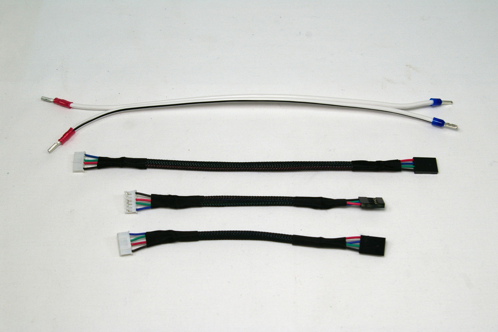
Connect the wiring looms to the Duet, as shown in the pictures below. Also refer to the wiring diagram above. You will need the following parts:
| # | Component | Qty | Type | |
| 1201 | DC cable – 250mm | 1 | Wiring |
|
| 477 | Motor loom – 160mm
(two in photo are 90mm) |
3 | Wiring |
| E0_TEMP – Hot end thermistor (green/blue, 2-way) | 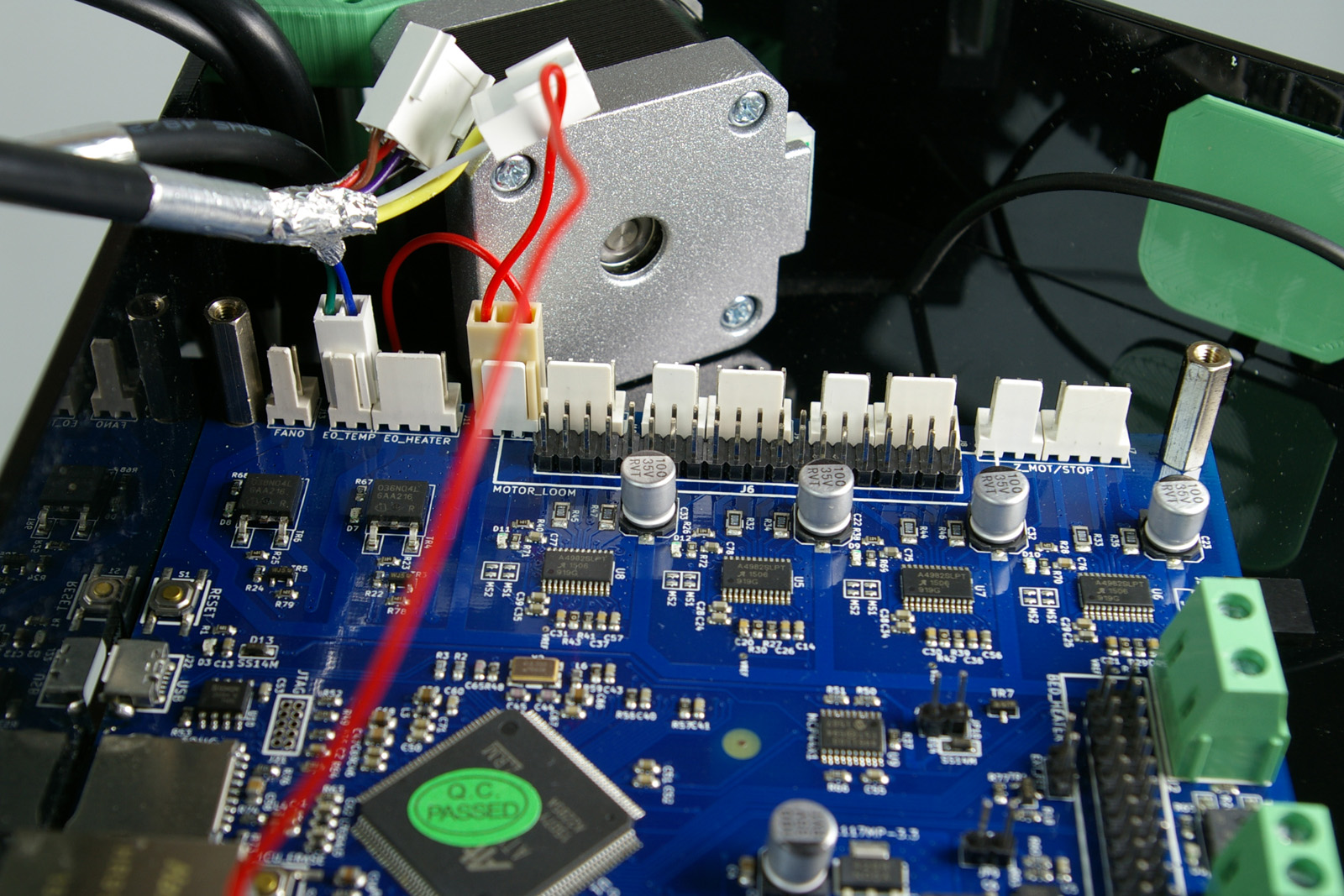 |
| E0_HEATER – Hot end heater (black/purple/red/brown, 4-way) | 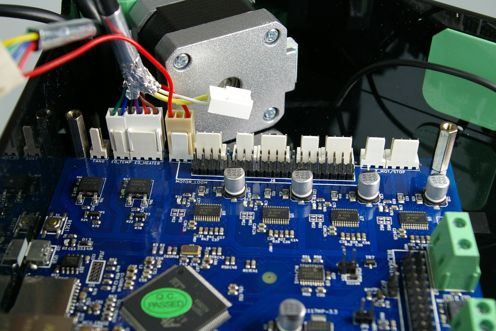 |
| Hot end fan (yellow/none/white, 3-way) NOTE: this connects to the double row of pins, NOT to ‘FAN0’. From the left, there should be two clear pins, then the yellow wire, another pin (covered by the housing, but not connected), then the white wire. FAN0, FAN1, FAN2 – NO CONNECTION! Do not connect anything to these pins The Fisher uses the “Always On Fan” pins. |
 |
| E0_MOT/STOP – (on first three pins) Bed probe (red/blank/red, 3-way). This was already fitted in the bed probe wiring step. | 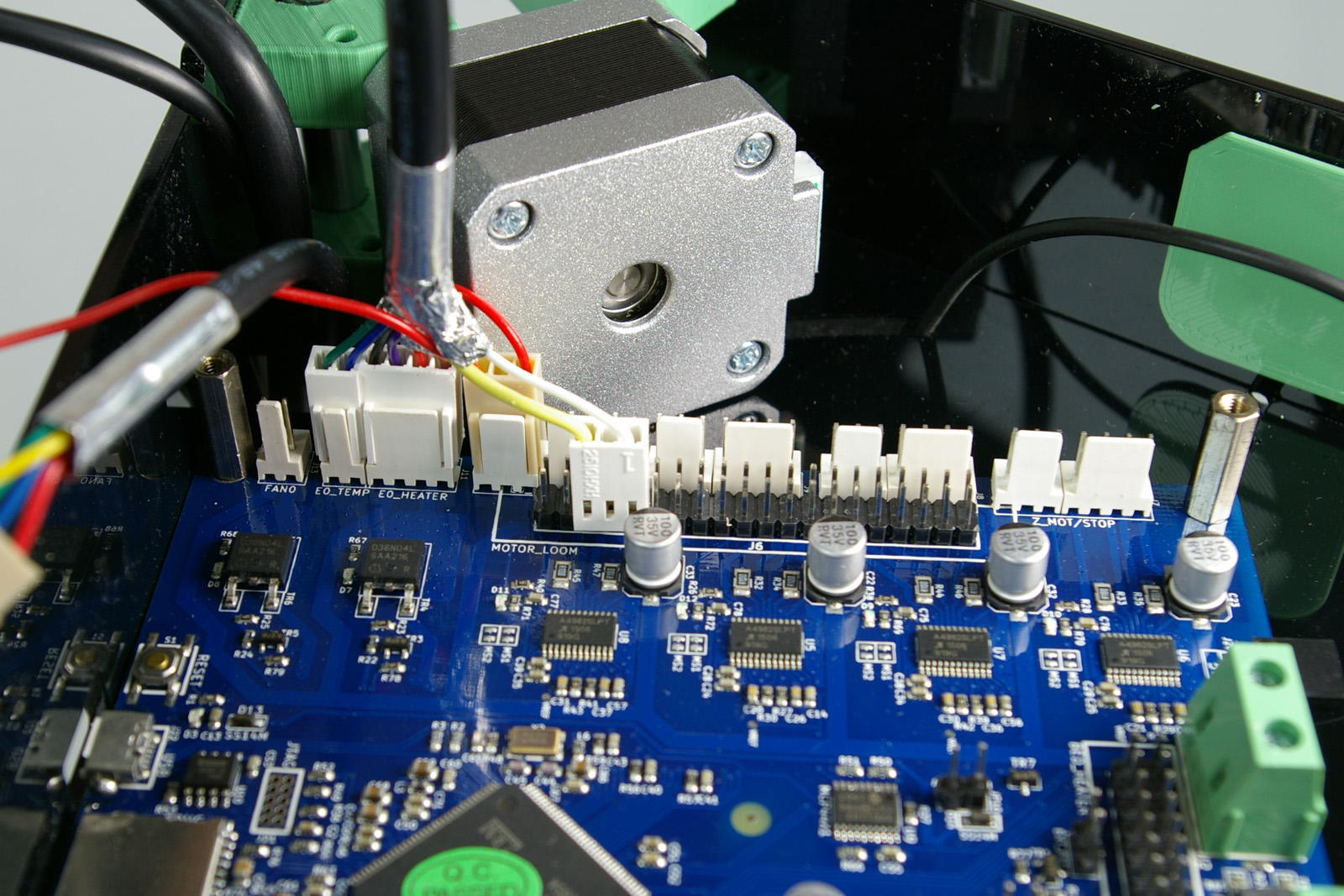 |
| E0_MOT/STOP – (on the other four pins) Extruder drive motor (yellow/green/blue/red, 4-way) | 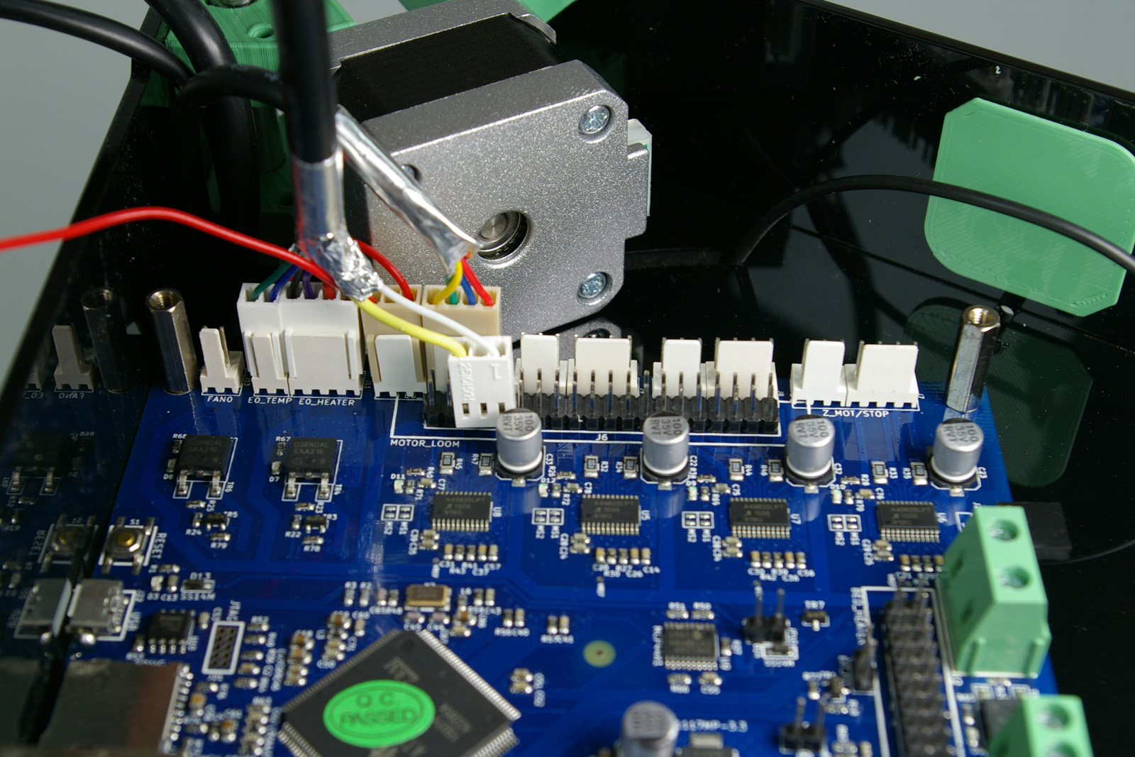 |
| X_MOT/STOP – X endstop (blue, space, red, 3-way) This is the SHORTEST endstop loom. | 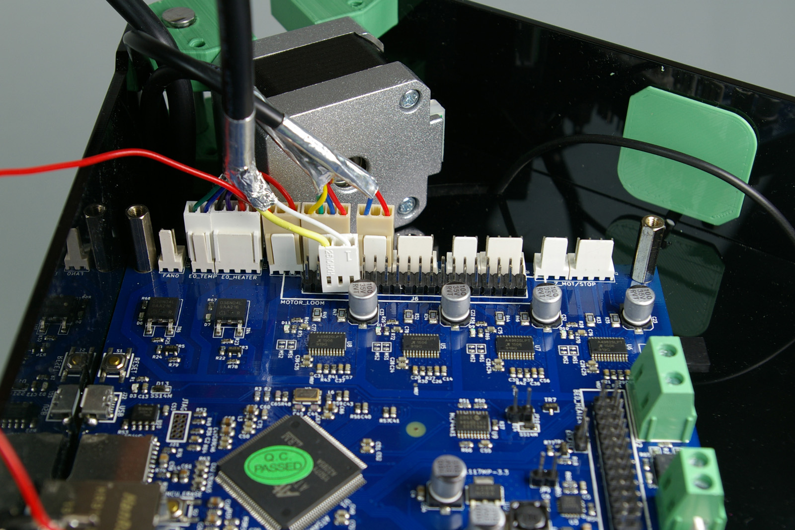 |
| X_MOT/STOP – (on the other four pins) X motor (black/green/blue/red, 4-way) Now connect the X motor to the Duet, using a 90mm motor loom. This is the motor closest to the motor connection pins on the Duet. Check that the endstop at the top of this tower is the one connected next to the X motor. |
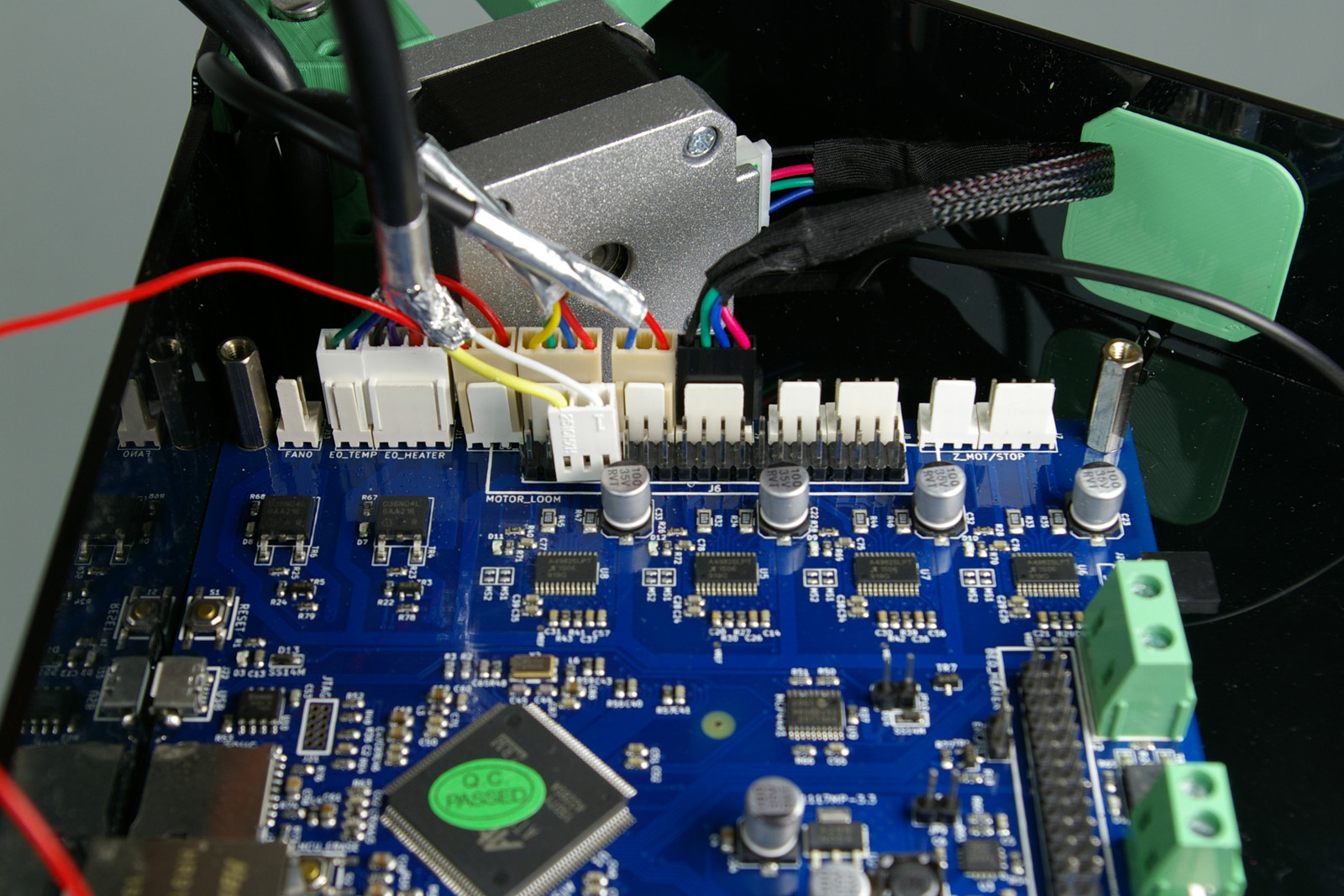 |
| Y_MOT/STOP – Y endstop (blue, space, red, 3-way) This is the LONGEST endstop loom. | 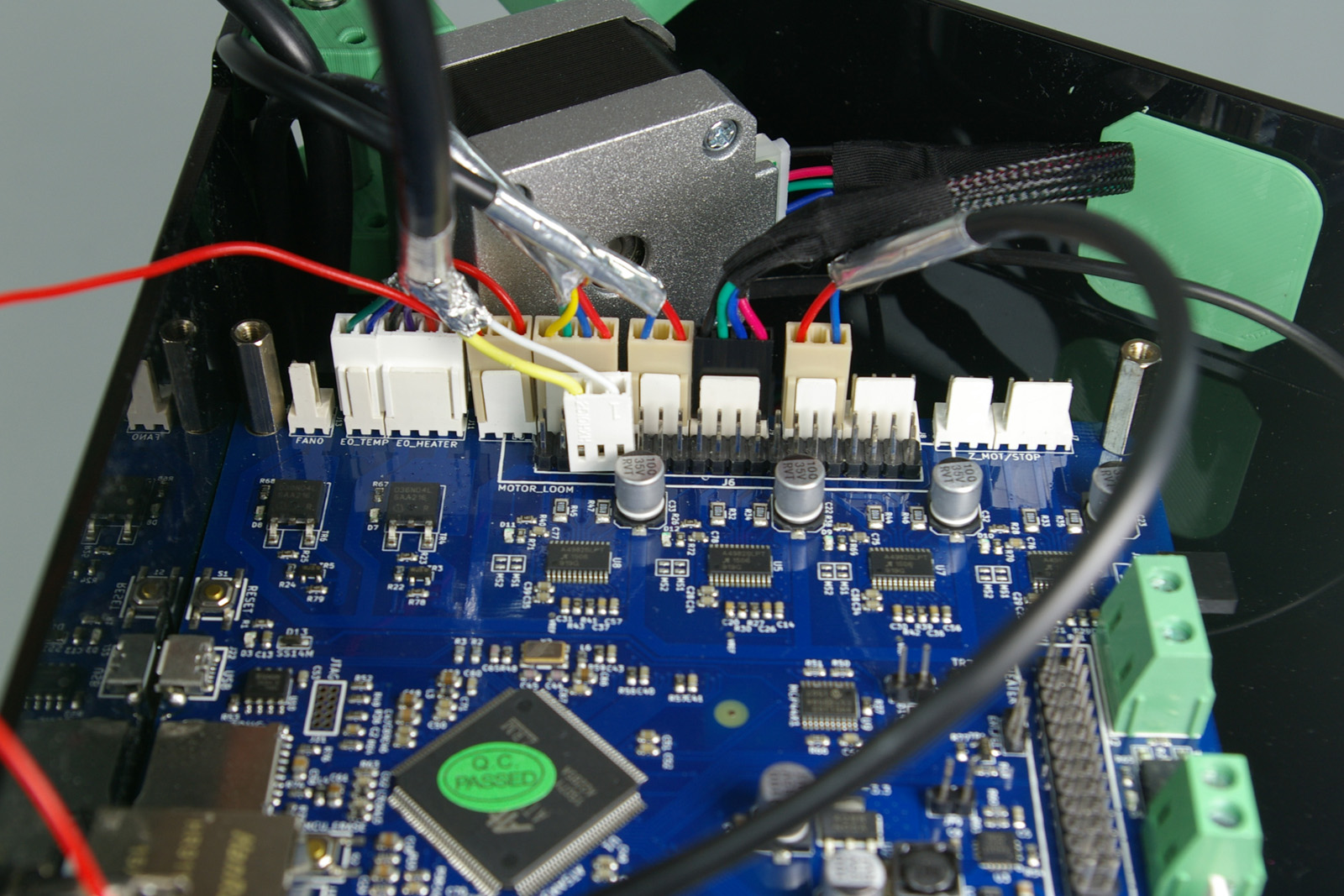 |
| Y_MOT/STOP – (on the other four pins) Y motor (black/green/blue/red, 4-way) Next the Y motor, using a 90mm motor loom. This is the motor nearest the large screw terminals on the end of the Duet board. Check that the endstop at the top of this tower is the one connected next to the Y motor. |
 |
| Z_MOT/STOP – Z endstop (blue, space, red, 3-way) This is the MEDIUM length endstop loom. | 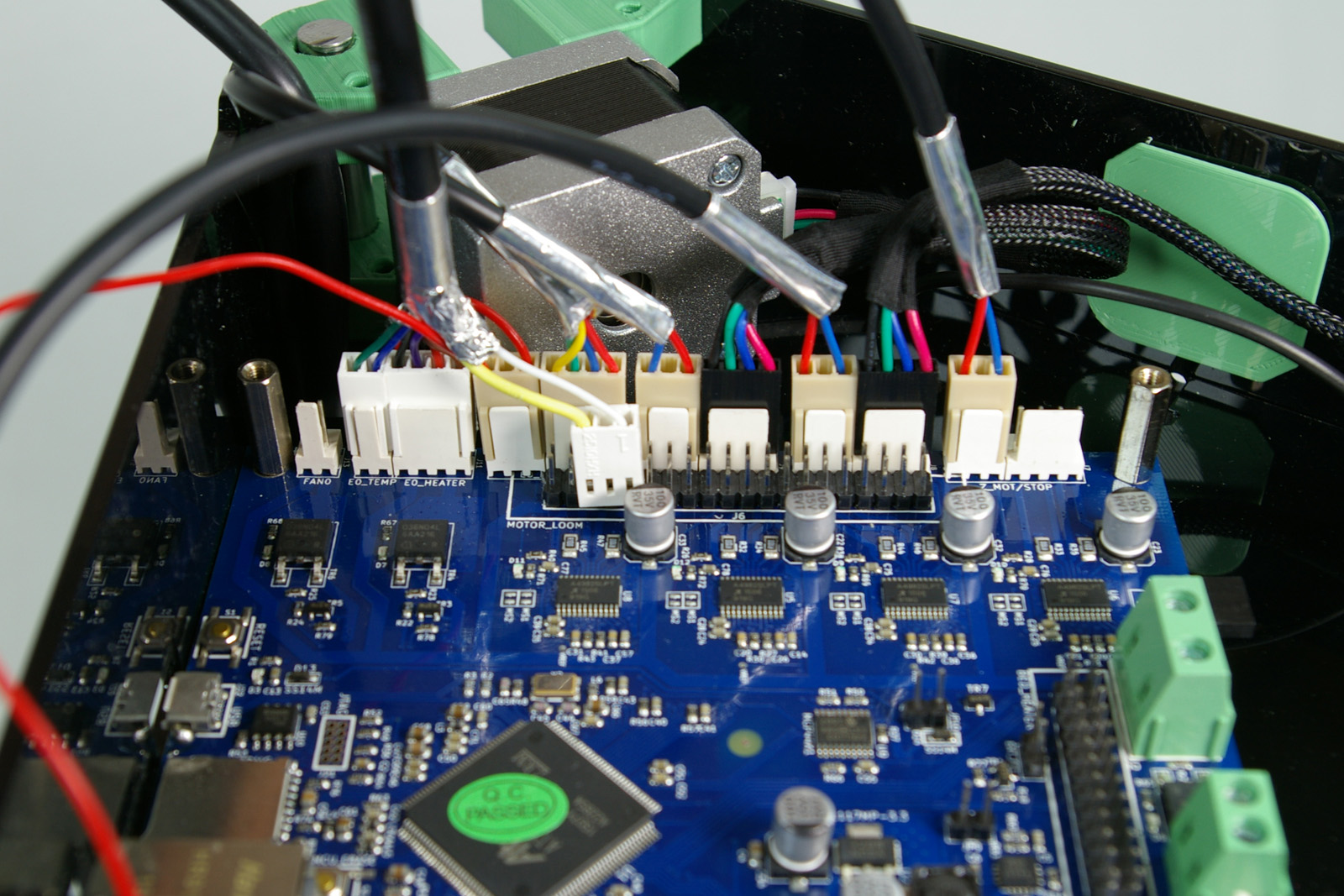 |
| Z_MOT/STOP – (on the other four pins) Z motor (black/green/blue/red, 4-way) Now the Z motor, using the 160mm motor loom. This is the motor nearest the ethernet socket on the Duet. Check that the endstop at the top of this tower is the one connected next to the Z motor. |
 |
| All the wiring connections fitted. | 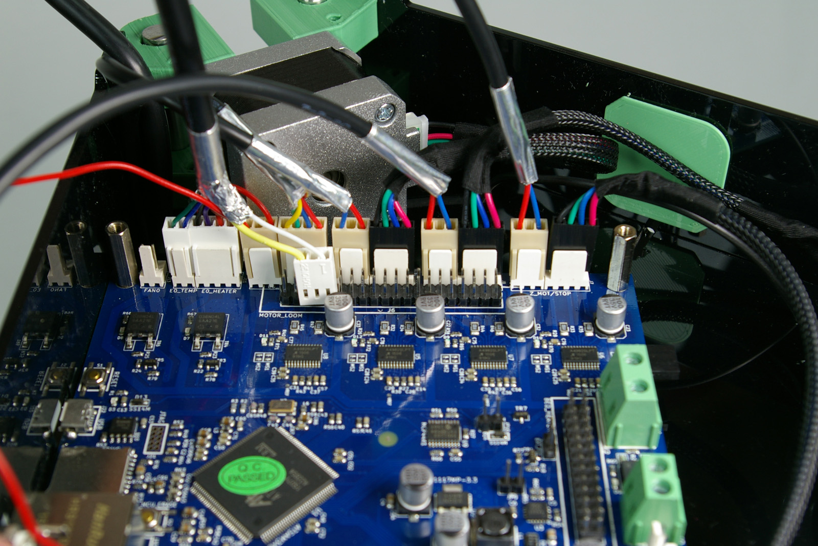 |
| This picture shows the motor connections, and orientation. If you have put the motor on the wrong way around, you can turn the motor around, to make the motor wiring easier. Unscrew the four motor screws, and turn the motor around, then retighten the screws. | 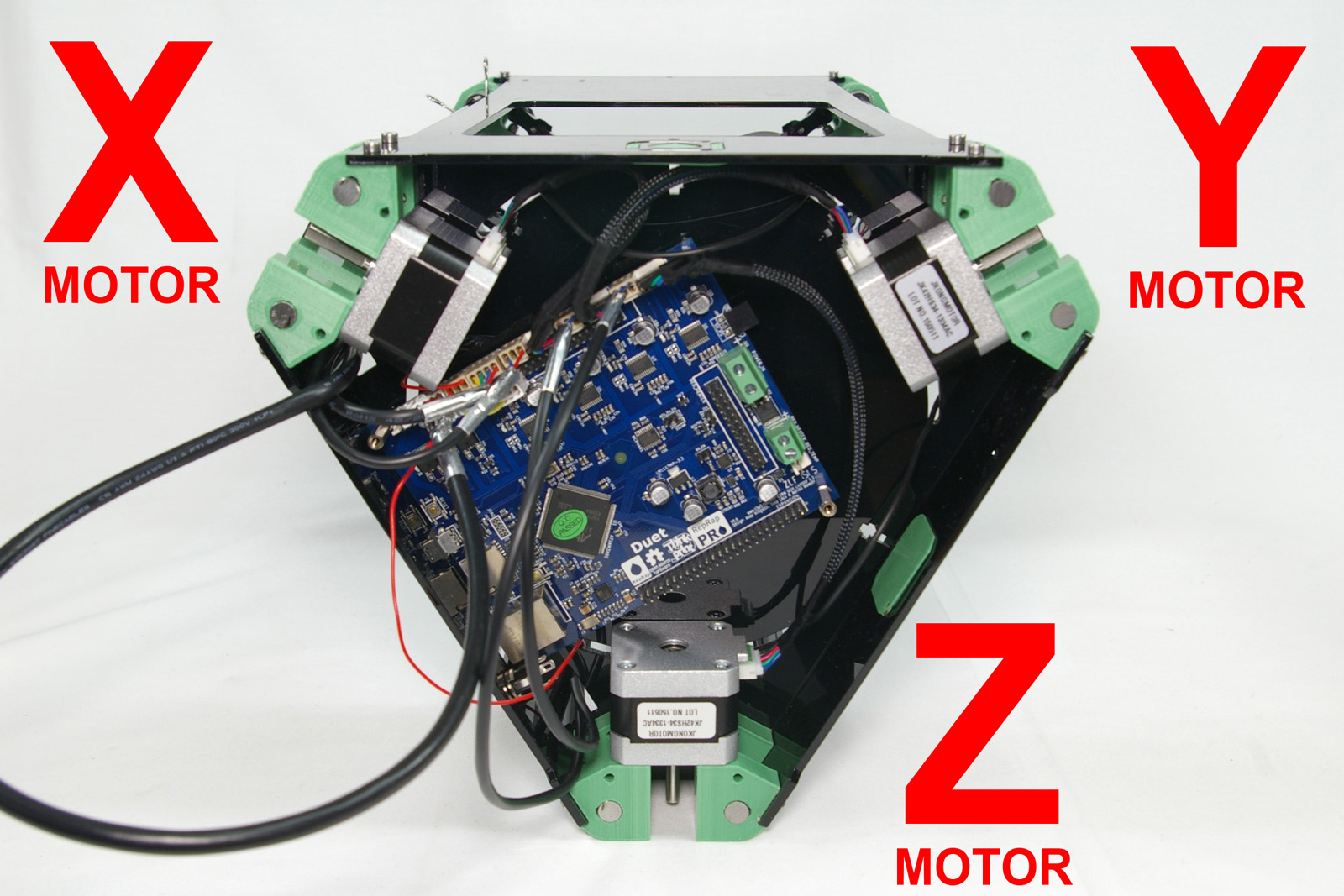 |
| Finally, connect the DC power cable. One of the cores has a black stripe running along it’s length. Connect this to the negative terminal (on the left hand side as viewed in the photograph). | 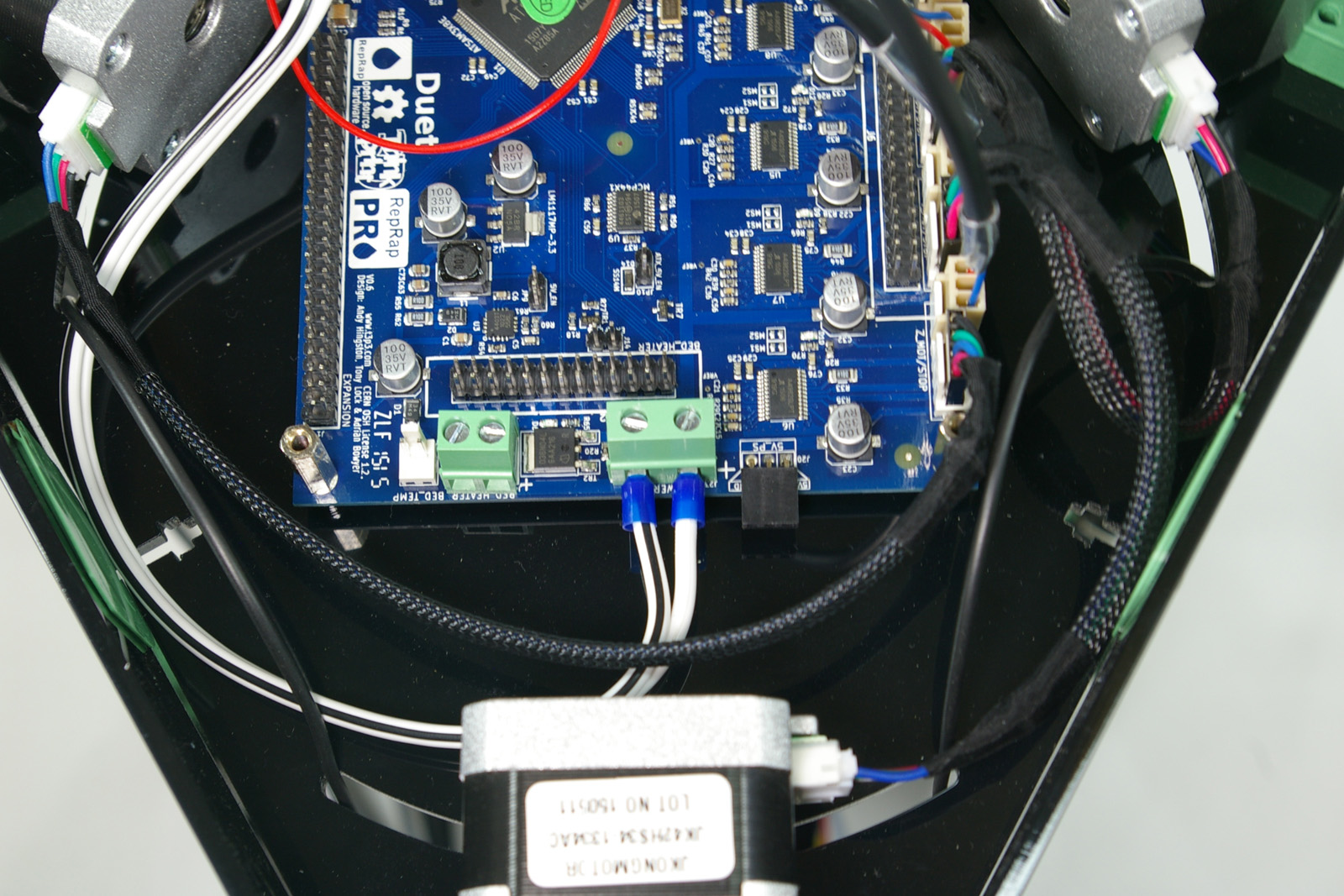 |
| Connect the DC power cable to the tabs on the back of the jack. | 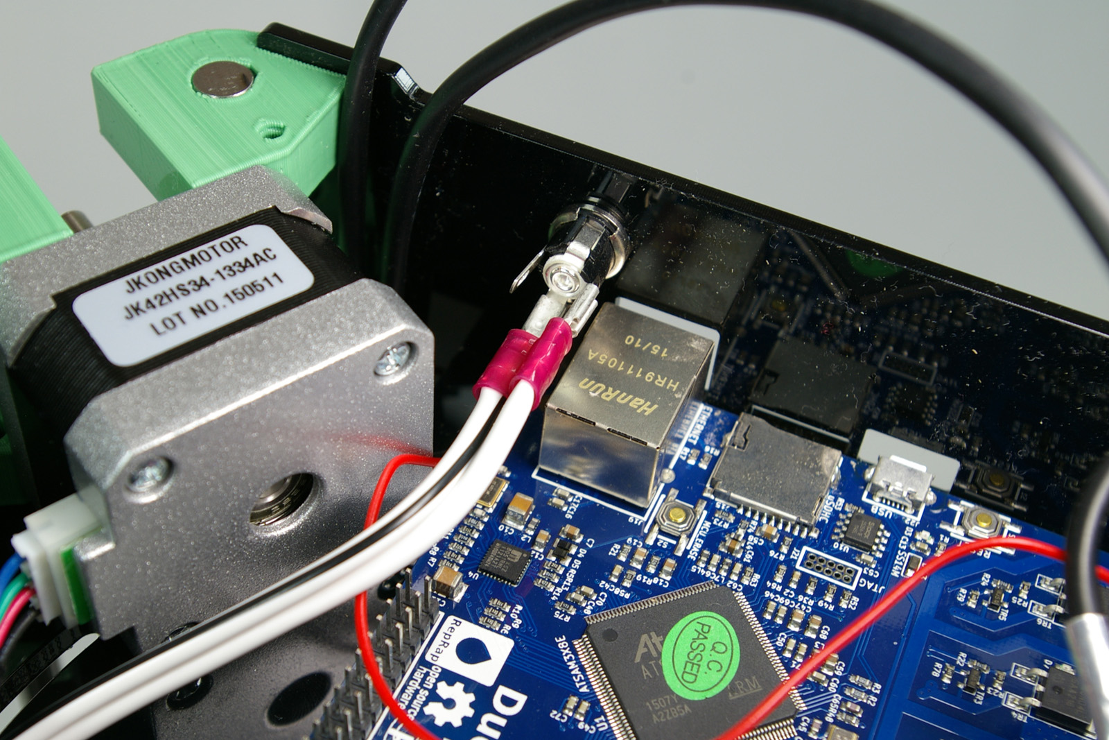 |
| Ground is the centre of the three tabs (the wire with the black stripe should connect to this), and positive is the tab that connects to the centre pin. Fit them with the ‘curly’ part of the crimp outwards. | 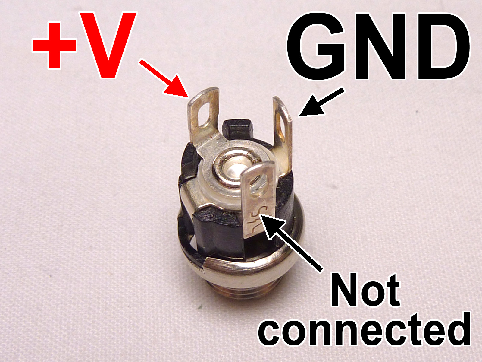 |
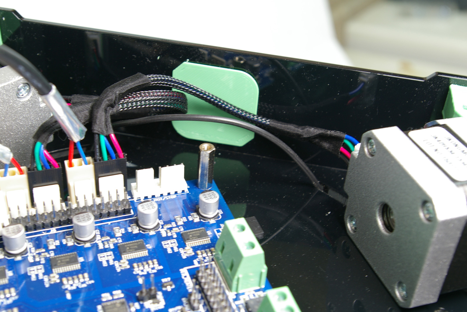
| With all the wiring fitted, tidy up the wiring so that it all fits below the level of the acrylic side panels. You can use a couple of cable ties to help. | 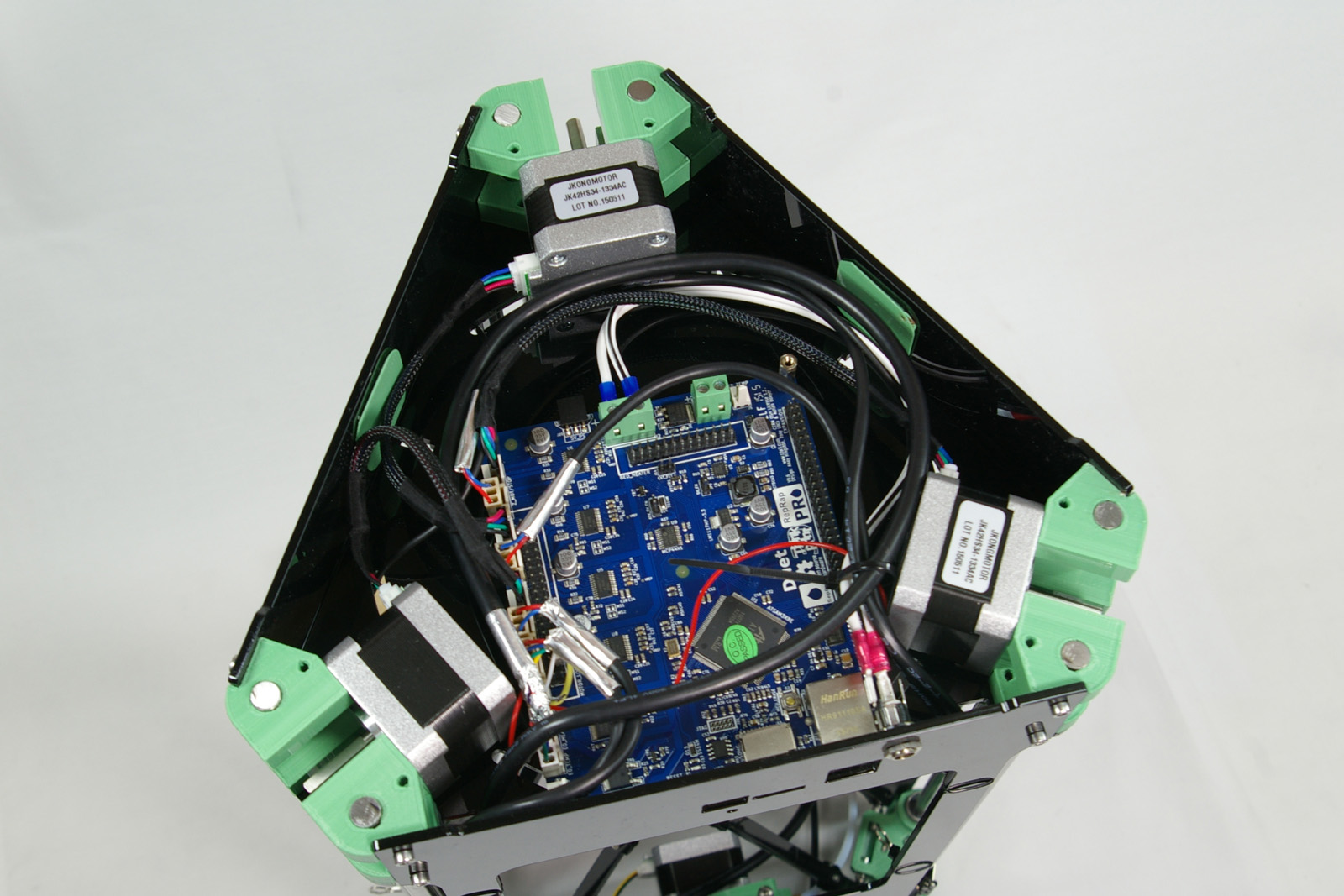 |
Jumper
You will need the following parts:
| # | Component | Qty | Type | |
| Fisher | 1 | Part-assembled | 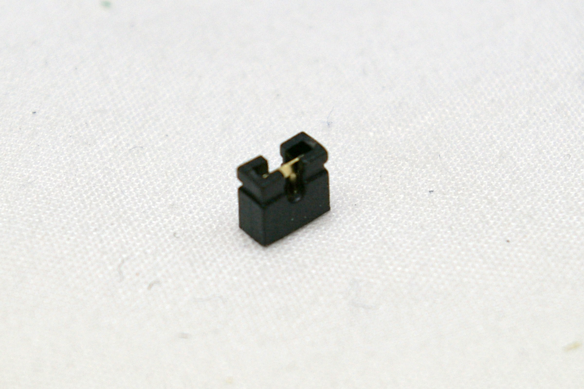 |
|
| 285 | PCB Jumper | 1 | Electronics |
| Fit the jumper onto the 5V_EN (JP9) header pins (location highlighted in the picture). This uses the on-board 5V regulator to supply power to the main processor of the Duet when 19V power is connected. | 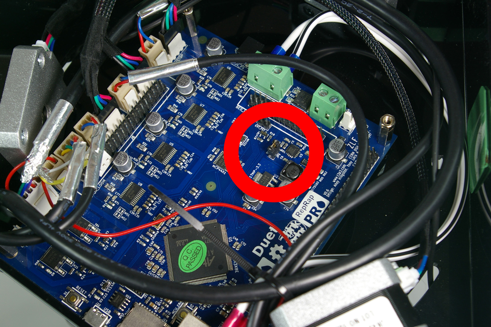 |
| A close up of the jumper position. | 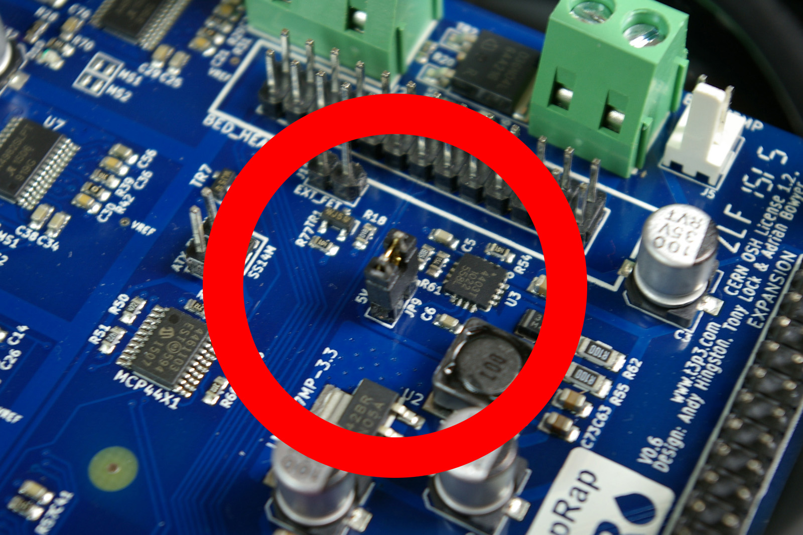 |
Back – Hot End Assembly Next – Bed, Top Plate and Belts